background image

1586A 

Users Manual 

3-12 

Basic Channel Operations 

Use the instructions in this section to perform basic channel operations.  

Open the Channel Setup Menu 

The Channel Setup menu lets the user manage channels, verify inputs, and also set up 
tests. To open the menu, push


on the front panel.  

To select channels, use the 

 and 

 arrow keys. To quickly move up and down the list 

of channels, use the 

 and 

 arrow keys. 

Note 

The Channel Setup menu cannot be accessed while a scan is in progress.  

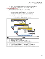
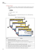
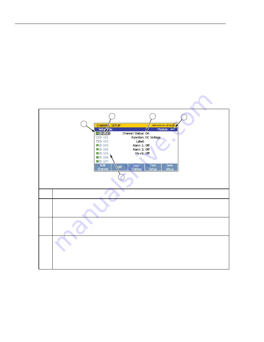
Table 3-3. Channel Setup Menu 

1

4

3

2

5


hcn017.eps

Item Function 


Module indicator that has two bars to show which Input Modules are connected and registered. 
The top indicator is slot 1 and the bottom indicator is slot 2. When a module is in a slot, the 
indicator is green. When a slot is empty, the indicator is white. 


Channel status. When ON, the channel can be configured and the channel status indicator to the 
left of the channel is green. When OFF, the channel information is not shown and the channel 
status indicator is white.


List of available channels. Channels show in the list only when an Input Module relay card is 
installed in a slot or a DAQ-STAQ Multiplexer is connected. For example, Ch201 through Ch222 
will not show in the channel list until an Input Module relay card is installed into slot 2. 

Note 

Ch001 is always the front-panel terminals and always shows in the channel list. 


Summary of Contents for 1586A

Page 1: ...tions are subject to change without notice All product names are trademarks of their respective companies 1586A SUPER DAQ Precision Temperature Scanner Users Manual Via Acquanera 29 22100 Como tel 031...

Page 2: ...vice center to obtain return authorization information then send the product to that service center with a description of the difficulty postage and insurance prepaid FOB Destination Fluke assumes no...

Page 3: ...1 15 PRT RTD Temperature Accuracy 1 16 PRT RTD Measurement Characteristics 1 16 Thermistor 1 16 Thermistor Resistance Accuracy 1 16 Thermistor Temperature Accuracy 1 17 Thermistor Measurement Characte...

Page 4: ...tor Module 3 4 Wiring Safety and Considerations 3 5 3 Wire and 4 Wire Sense Input Configuration 3 6 Input Types and Wiring Diagrams 3 7 Input Wiring Instructions 3 8 Channel Configuration 3 10 About C...

Page 5: ...4 16 Overview 4 16 Configure an Automated Test 4 17 Connect to An External Source 4 18 Record 4 19 Record Measurement Data 4 19 Memory Consumption for Recorded Data 4 20 Open and View Measurement Dat...

Page 6: ...1586A Users Manual iv Error Messages 7 3 Troubleshooting 7 20...

Page 7: ...3 6 Thermocouple Channel Configuration 3 21 3 7 Thermistor Channel Setup 3 22 3 8 PRT Channel Setup 3 23 3 9 Totalizer Channel Configuration 3 26 3 10 Math Channel Formulas 3 27 3 11 Math Channel Conf...

Page 8: ...1586A Users Manual vi...

Page 9: ...ut Module Installed Shown 3 9 3 5 Example Channel Assignment 3 11 3 6 Channel Status Indicators 3 13 3 7 Zero Function 3 15 3 8 DIO Connector 3 24 3 9 Totalizer Input TOT 3 25 3 10 Rear Panel Alarm Ou...

Page 10: ...1586A Users Manual viii...

Page 11: ...ristics 1 16 Thermistor 1 16 Thermistor Resistance Accuracy 1 16 Thermistor Temperature Accuracy 1 17 Thermistor Measurement Characteristics 1 17 Thermocouple 1 18 Thermocouple Voltage Accuracy 1 18 T...

Page 12: ...1586A Users Manual 1 2 General 1 22 1586 2586 High Capacity Input Module Specifications 1 22 General 1 22...

Page 13: ...ddition the Product also has 20 math channels one DIO channel and one TOT channel that can be included in scan A scan can be manually controlled from the front panel or triggered with a variety of tri...

Page 14: ...record on each scan with a value range of 0 to 255 based on the port state when it is read Totalizer The Product is equipped with a unidirectional resettable totalizer with an input count capability o...

Page 15: ...tandby Key Puts the Product in the standby mode In standby the display is off and the keys are disabled Standby mode also disables remote operation See Power ON and Standby in Chapter 2 Function Softk...

Page 16: ...nce and temperature 4W Sense Terminals Sense input terminals to make 3 wire and 4 wire compensated resistance measurements Channel Status Indicator Square green box that shows when a channel is set to...

Page 17: ...kly configure and make measurements with the front panel inputs See Chapter 5 for DMM operation instructions Instrument Setup Configure the Product Menu contains many user configurable settings to cus...

Page 18: ...r remote operation See the 1586A Remote Programmers Guide Totalizer Input Input terminal for the Totalizer feature See Totalizer Channel Configuration in Chapter 3 DIO Digital I O Input Ports Eight di...

Page 19: ...ibution part of the building s low voltage MAINS installation CAT IV 1 Measurement Category IV is applicable to test and measuring circuits connected at the source of the building s low voltage MAINS...

Page 20: ...earth could put voltage on the chassis that could cause death Do not put the Product where access to the mains power cord is blocked Use only correct measurement category CAT voltage and amperage rate...

Page 21: ...se the Product around explosive gas vapor or in damp or wet environments Screen Capture Feature The Product can take a screenshot of the display and save it directly to the USB drive To take a screens...

Page 22: ...es information on error messages and how to troubleshoot the Product The Product Manual Set The Product manual set includes This 1586A Users Manual that contains feature information operation instruct...

Page 23: ...ration and Repair Information To schedule and send the Product to Fluke for calibration or repair 1 Contact the Fluke Service Center in your area to schedule the calibration or repair see Contact Fluk...

Page 24: ...xternal trigger input alarm remote bus manual automated test Memory Scan data RAM 75 000 readings with timestamp Data Setup flash memory 20 MB USB Host Port Connector type Type A Function Memory File...

Page 25: ...3 wire none Source Current Reversal Interval 0 to 400 range Fast sample rate 2 ms Medium sample rate 250 ms Slow sample rate 250 ms Maximum Lead Resistance 4 wire 2 5 of range per lead for 400 and 4...

Page 26: ...0 018 C 0 03 C add 0 01 C 0 0028 C 600 C 0 026 C 0 045 C add 0 01 C 0 0034 C PRT RTD Measurement Characteristics Range Temperature Display Resolution Source Current Slow Medium Sample Rate Fast Sampl...

Page 27: ...add 0 05 C 100 C 0 047 C 0 114 C 0 28 C add 0 34 C 150 C 0 23 C 0 56 C 1 34 C add 1 7 C Temperature Accuracy 5 k Thermistor Slow Sample Rate Medium Sample Rate Fast Sample Rate 2 wire 40 C 0 003 C 0 0...

Page 28: ...outside the specified environment temperature range Accuracy with fixed external CJC does not include the accuracy of the reference junction temperature Linear interpolation may be used between point...

Page 29: ...C 1200 C 2000 C 0 22 C 0 26 C 0 39 C 0 32 C 0 36 C 0 53 C 0 34 C 0 39 C 0 56 C 0 44 C 0 49 C 0 69 C G 0 C to 2315 C 600 C 1200 C 2000 C 0 24 C 0 22 C 0 33 C 0 36 C 0 32 C 0 46 C 0 36 C 0 32 C 0 46 C 0...

Page 30: ...0 0025 0 0007 add 2 V add 0 0008 of range 0 0005 0 0001 10 V 0 0024 0 0005 add 0 0008 of range 0 0005 0 0001 50 V 0 0038 0 0012 add 0 0008 of range 0 0005 0 0001 DC Voltage Input Characteristics Rang...

Page 31: ...the accuracy specification If the environment temperature is outside the specified range multiply the Temperature Coefficient numbers by the temperature deviation and add to the accuracy specification...

Page 32: ...20 bits Trigger Absolute Voltage Range 4 V to 30 V Minimum Logic High 2 0 V Maximum Logic Low 0 7 V Minimum Pulse Width 50 s Maximum Latency 100 ms Alarm Output Absolute Voltage Range 4 V to 30 V Outp...

Page 33: ...t the Regional Voltage 2 3 Connect to Mains Power 2 4 Set the Handle Position 2 5 Power On and Standby 2 6 Warm Up the Product 2 7 Configure the Product 2 7 Input Module and Relay Card Installation 2...

Page 34: ...1586A Users Manual 2 2...

Page 35: ...an illustration on how to set the voltage selector See Chapter 6 for instructions on how to change the fuse Each voltage selection requires a specific fuse See Table 2 1 Table 2 1 Fuses Voltage Select...

Page 36: ...Replace the mains power cord if the insulation is damaged or if the insulation shows signs of wear Make sure the ground conductor in the mains power cord is connected to a protective earth ground Disr...

Page 37: ...d as a stand Figure 2 3 shows the various handle positions and also shows how to remove and install the handle and the protective rubber boots Carrying Position Viewing Position Alternate Viewing Posi...

Page 38: ...forms a self check This self check can take up to 2 minutes to complete and if the Product detects any errors an error message is shown on the display that contains the error description along with an...

Page 39: ...on the display to edit the settings Table 2 2 shows the menu items and selections available in the Instrument Setup menu Table 2 2 Instrument Setup Menu Menu Item Description Selections Available Lan...

Page 40: ...annel relays have been scanned along with the name serial number and calibration date of the Input Module Input Module and Relay Card Installation Before an Input Module can be inserted into the rear...

Page 41: ...y card was installed 3 Power on the Product with the main power switch 4 Verify that the module indicator appears green on the main screen see Figure 2 5 Note If the module indicator is not green the...

Page 42: ...1586A Users Manual 2 10 2 3 4 1 hcn018 eps Figure 2 6 Relay Card Installation...

Page 43: ...o the Product until the card is fully seated Caution Do not force the card into the slot The card should easily move when the rails of the relay card are properly inserted in the slot guides 7 Install...

Page 44: ...1586A Users Manual 2 12 hcn032 eps Figure 2 7 DAQ STAQ Multiplexer Installation...

Page 45: ...ts See Chapter 6 To change passwords of the User profiles The User profiles sole purpose is to produce secure data files that are traceable back to the user who performed the test commonly referred to...

Page 46: ...1586A Users Manual 2 14...

Page 47: ...Verify a Channel 3 14 Zero a Channel 3 14 Copy a Channel 3 15 Save or Load a Channel Configuration Setup File 3 16 Reset the Channel and Test Configuration 3 18 Analog Channel Configuration Ch001 Ch1...

Page 48: ...1586A Users Manual 3 2...

Page 49: ...that can be configured to measure temperature resistance and dc volts and two low burden current channels ChX21 and ChX22 that measure dc current without the use of an external shunt resistor Note To...

Page 50: ...external bench top accessory that is used to quickly wire inputs of various types to the Product see Figure 3 2 Each Multiplexer has 20 analog channels ChX01 through ChX20 that can be configured to m...

Page 51: ...ces before an input module is opened Use the correct terminals function and range for measurements Make sure proper insulation is maintained between channel wiring terminations and that no loose stran...

Page 52: ...wires must be connected to channels ChX01 through ChX10 and the sense wires to the set of terminals directly across from where the source is connected channels ChX11 through ChX20 Note The Product wi...

Page 53: ...nected directly across from source on Channel 116 Note For 3 Wire connections leave the H sense open hcn014 eps Figure 3 3 3 Wire and 4 Wire Channel Reservation Input Types and Wiring Diagrams Table 3...

Page 54: ...or 2 Wire or 4 Wire Types R T 2 2 252 k 5 k 10 k Page 3 22 Thermocouple Types B C D E G J K L M N R S T U W POLY 2 Page 3 21 H L Note 1 Each Input Module has two terminal sets mA 21 and mA 22 that are...

Page 55: ...ubber wire compressor used to secure the wires can be removed for more room 6 Close the Input Module cover and rotate the cover locks to the locked position 7 Align the Input Module on the guide rails...

Page 56: ...ut terminal 4 04 in the Input Module and then slid into slot 1 The channel is Ch104 A thermistor source is connected to input terminal 8 08 in the Input Module and then slid into slot 2 The channel is...

Page 57: ...11 0 1 2 3 4 5 6 7 0 1 2 3 4 5 Slot Channel 101 122 Slot Channel 201 222 Rear View Front View 1586A T DAQ PREC 1 2 3 4 5 6 7 8 1 2 3 4 5 6 Input Module Terminal Number Channel 106 Rear Panel Slot Cha...

Page 58: ...which Input Modules are connected and registered The top indicator is slot 1 and the bottom indicator is slot 2 When a module is in a slot the indicator is green When a slot is empty the indicator is...

Page 59: ...can monitor or record an input the associated channel must be set to ON and configured When a channel is set to ON it is referred to as active The channel indicator appears green when set to ON and wh...

Page 60: ...el menu 7 Evaluate the measurement and zero the channel if necessary See Zero a Channel Zero a Channel In certain applications it may be necessary to zero the channel in order to make measurements wit...

Page 61: ...page 3 30 for instructions Relative Measurement Value Baseline Measurement Zero Function Softkey Mx B Indicator hcn060 eps Figure 3 7 Zero Function Copy a Channel The Product has a copy and paste func...

Page 62: ...aved to or loaded from the USB drive To save Setup files to a USB drive save the file to the internal memory then copy it to the USB drive To load a Setup file from a USB drive copy the file to intern...

Page 63: ...rnal files 3 Select Setup Files then push 4 Use and to highlight the Setup File 5 Push to load and use the Setup File To load a Setup File from a USB drive 1 Insert a USB drive into the front panel US...

Page 64: ...the previous configuration for channels previously configured A channel can be configured with the Edit Channel softkey in the Channel Setup menu Each channel has independent channel options such as C...

Page 65: ...the Product current sources can also be connected to ChX01 through ChX20 by the use of an accessory shunt resistor See Chapter 2 for part number and ordering information Table 3 4 Current and Voltage...

Page 66: ...channel for a 2 wire or 4 wire resistance measurement connection See Sense Input Configuration on page 3 6 Set the range to Auto 100 1 k 10 k 100 k 1 M or 10 M Ch001 can be set to 100 M Input a custo...

Page 67: ...e correction in millivolts If the correction is not used leave the coefficients set to 0 Table 3 6 Thermocouple Channel Configuration 1 2 3 4 5 6 hcn009 eps Item Function Thermocouple function selecti...

Page 68: ...t to 0 Table 3 7 Thermistor Channel Setup 1 2 3 4 5 6 7 hcn010 eps Item Function Thermistor function selection Select the thermistor type Types available R T 2 252 k 5 k and 10 k Set up the channel fo...

Page 69: ...Channel Setup 1 2 3 4 5 6 7 8 hcn011 eps Item Function PRT function selection Select the PRT type Types available ITS90 CVD PT 385 and PT 392 Set the PRT resistance value at 0 C CVD PT 385 or PT 392...

Page 70: ...ir decimal equivalents are shown below 11111111 is represented by decimal 255 00001111 is represented by decimal 15 00010001 is represented by decimal 17 10000101 is represented by decimal 133 Notes F...

Page 71: ...command The default totalizer mode is read In read mode the count is not effected when read during the scan sweep or read by remote command In read reset mode the totalizer count is automatically res...

Page 72: ...n in Table 3 9 If the channel was previously configured push to cancel the configuration sequence to use the last channel configuration 3 Use the information in Table 3 9 to configure the totalizer ch...

Page 73: ...at is configured to calculate a polynomial function of an input channel Table 3 10 Math Channel Formulas Formula Equation Description Polynomial C6A 6 C5A 5 C4A 4 C3A 3 C2A 2 C1A C0 Calculates a polyn...

Page 74: ...ill be OL Average 1 A1 A2 A3 N Calculates the arithmetic mean of the readings of selected channels Maximum 1 N A Finds the maximum reading among selected channels Minimum 1 N A Finds the minimum readi...

Page 75: ...nd B are shown in the example because the sum math formula only combines two channels Some formulas have only one source channel while some others allow more than two source channels Set the unique un...

Page 76: ...r the gain is calculated the B value or the offset is added to the resultant For example if a channel measures a voltage of 3 volts and the gain was set to 3 3 the measurement on the display would rea...

Page 77: ...lculate the result with the entered gain and offset values See the examples in this section Temporarily set the gain to 1 and the offset to 0 to verify that the measurements are in the expected range...

Page 78: ...TRIG Function Ground Terminal Alarm Output 1 Alarm Output 2 Alarm Output 3 Alarm Output 4 Alarm Output 5 Alarm Output 6 External Trigger Input hcn049 eps Figure 3 10 Rear Panel Alarm Outputs 0 1 2 3...

Page 79: ...00 seconds Rate of Change Rate of Change is a statistical calculation that shows the user how much a measurement value has changed over a period of time The Rate of Change is viewed in the statistics...

Page 80: ...ct to automatically detect an open circuit in the probe This setting only shows in a thermocouple channel Probe Library The Probe Library lets users quickly load and save thermistors thermocouples and...

Page 81: ...push 3 Push or to select Function then push 4 Push to open the Probe Library 5 Push or to highlight a probe in the list then push to edit 6 Select Label and push to change the label 7 Select Function...

Page 82: ...1586A Users Manual 3 36...

Page 83: ...4 10 Automatic Power Loss Scan Resume 4 11 Basic Scan Procedures 4 11 Start a Scan 4 11 View Scan Data and Statistics 4 12 Graph the Measurements 4 14 Monitor 4 15 Automated Test 4 16 Overview 4 16 Co...

Page 84: ...1586A Users Manual 4 2...

Page 85: ...or function does not interrupt the active scan and only shows the measurement data from the last scan cycle completed In order for the Product to scan the applicable channels need to be active and the...

Page 86: ...an status and progress of the scan Table 4 1 shows the Scan menu and describes the status indicators and functions that can be performed from this menu To open the Scan menu push on the front panel Ta...

Page 87: ...long with helpful statistics See View Scan Data and Statistics on page 4 12 Pause a scan after it is started The softkey is not visible when the scan is inactive Start or stop a scan See Start a Scan...

Page 88: ...gger type to Timer and setting an interval time Channel List SCAN START Channel 102 Channel 104 Channel 115 Channel Delay Set Channel 117 Channel Delay Set Channel 121 Sample Time Key Consists of NPLC...

Page 89: ...when a set TRIG input on the Digital I O port detects a low condition Like Interval the user manually sets the number of times to scan Scan Count and the time between the scans Interval The Alarm trig...

Page 90: ...manage the scan data files on the USB drive connect the USB drive to a PC and open the folder named Scan See Open and View Measurement Data on a PC on page 4 20 Sample Rate The Sample Rate sets the sp...

Page 91: ...test commonly referred to as test traceability This is necessary for test environments and applications that require a method to guarantee that the test data has not been forged changed or tampered wi...

Page 92: ...For example a reference probe that is fully calibrated is put into a chamber with other probes that reads 250 52 C With the align function the user sets the calibrated reference probe channel to be t...

Page 93: ...paused or stopped before the Channel Setup or the Instrument Setup menu can be accessed 1 Configure the Test Setup See Configure a Scan on page 4 6 2 Set all channels to be scanned to ON See Set Chan...

Page 94: ...h to record data For the Automated Test trigger type Push then push to start the test The Product reads the setpoint information and automatically starts a scan sweep when the setpoint parameters Setp...

Page 95: ...a set of data from its mean The more spread apart the data the higher the deviation Peak to Peak Difference between the Maximum and the Minimum Rate of Change A measure of how much the readings change...

Page 96: ...or more channels with different input types such as temperature and milliamps can make the graph difficult to read because they do not share the same unit To prevent this only select channels of the s...

Page 97: ...nnel push on the Scan menu When a scan is in progress the display shows the measurement from the last reading If a scan is not in progress the display shows a real time measurement hcn053 eps Figure 4...

Page 98: ...232 connection on the rear panel see Figure 4 7 The source is then activated and sets the temperature to the setpoint When the measurement from the reference temperature probe that is wired to the Pr...

Page 99: ...d channels in ascending channel order followed by the optional second reference channel Ref2 For example Ref1 Ch102 Ch103 Ch104 Ref2 Alternate Reference This scan sequence will scan the first referenc...

Page 100: ...em and the peak to peak value of the measurement is less than 0 05 C for 10 minutes because of the 0 05 C Stability and the 10 minute Soaktime Sets the duration in minutes that each of the programmed...

Page 101: ...scan data when the scan is started If set to OFF the user must manually push to record scan data to file after the scan is started Note Auto Recording is associated only with the Scan Monitor function...

Page 102: ...o a PC where the results can be viewed in Microsoft Excel To open the a data file on a PC 1 Put the data on the USB drive to be transferred to the PC If the Data file is on the internal memory copy th...

Page 103: ...Month Year Hour Minute Seconds Milli seconds hcn047 eps Figure 4 8 Scan Data File Name Convention 6 Choose a file to open then double click on the file The time stamped data folder contains two comma...

Page 104: ...cussed and shown in the subsequent sections General Information This section of the spreadsheet shown below contains general information on the scan performed such as the start time and the Operator I...

Page 105: ...igital Channels This section of the spreadsheet shown below contains configuration information for the DIO channel and the TOT channel Math Channels This section of the spreadsheet shown below contain...

Page 106: ...r a single scan sweep and shows the time when the sweep completed To see how the test and channels were configured view the information in the setup csv file see How to Read the Setup csv File All mea...

Page 107: ...M Operation Title Page Introduction 5 3 About the Measure Function 5 3 About the DMM Function 5 3 Input Type Selection and Range Adjustment 5 4 Relative Measurements 5 4 Graph the Measurements 5 5 Mea...

Page 108: ...1586A Users Manual 5 2...

Page 109: ...urces are ignored About the DMM Function The DMM is a digital multimeter feature lets users quickly connect test leads to the front panel to make voltage resistance current and temperature measurement...

Page 110: ...lative function that lets the user make relative measurements A relative measurement is the difference above or below a baseline measurement value To make a relative measurement a measurement is made...

Page 111: ...et the user evaluate the data on the display The graph automatically scales to fit all the information on the display when opened To refine the data the graph can be manipulated with the arrow keys as...

Page 112: ...ore Softkey hcn056 eps Figure 5 5 DMM Statistics Table 5 1 Statistics Statistic Description Maximum Maximum measurement Minimum Minimum measurement Average Average of all the measurements taken Standa...

Page 113: ...6 1 Chapter 6 Maintenance and Care Title Page Introduction 6 3 Clean the Product 6 3 Replace the Fuse 6 3 Memory Reset and Factory Reset 6 4 User Replaceable Parts and Accessories 6 5...

Page 114: ...1586A Users Manual 6 2...

Page 115: ...fuse that protects from overcurrent Each voltage selection requires a specific fuse See Table 6 1 Warning To prevent possible electrical shock fire or personal injury use only specified replacement pa...

Page 116: ...s Note All memory reset functions require the Admin password to accomplish Table 6 2 Comparison of the Memory Clear Functions Task Clear All Files Factory Reset Deletes Test Setup files DMM Data files...

Page 117: ...ty Contact Fluke Transit Case 1 Contact Fluke OPC Server software for 1586A 1 Contact Fluke DIO ALARM connectors for 1586A 1 4298499 USB Cable 1 4121552 USB Drive 4 GB 1 4298486 RS 232 Cable 1 2675487...

Page 118: ...1586A Users Manual 6 6...

Page 119: ...7 1 Chapter 7 Error Messages and Troubleshooting Title Page Introduction 7 3 Error Messages 7 3 Troubleshooting 7 20...

Page 120: ...1586A Users Manual 7 2...

Page 121: ...Cause A discrete parameter was received that was not a valid choice for this command Solution Invalid parameter value used Check the parameter values and try again Error 222 Data out of range Cause A...

Page 122: ...large for this command Solution Check the parameter value and try again Error 113 Undefined header Cause A command was received that is not valid for this instrument Solution The command entered coul...

Page 123: ...ync with inguard Solution Instrument will restart the GX Error 103 Inguard not responding send Cause Inguard not responding send Solution Instrument will restart the GX Error 104 Oversize packet recei...

Page 124: ...in contact Fluke see Chapter 1 Error 201 Error detecting line frequency Cause The line frequency is out of range Solution Cycle the power If the error occurs again contact Fluke see Chapter 1 Error 20...

Page 125: ...nnel list and make sure all selected channel are set up correctly Error 300 Invalid procedure Cause Wrong calibration procedure is specified in CALibrate STARt command or MAIN in CALibrate STARt comma...

Page 126: ...r occurs again contact Fluke see Chapter 1 Error 322 Password missing Cause CALibrate ENABle command was received to unlock the calibration but ADMIN password is not provided Solution Make sure that A...

Page 127: ...external CJC first Error 402 TC external reference channel Cause Configure the lowest module channel as TC with external CJC Solution Check the parameter and make sure that the lowest module channel i...

Page 128: ...igned Solution Assign a channel as reference channel Error 410 Alarm channel not set Cause A scan is started but the alarm trigger does not have an alarm channel assigned Solution Assign a channel as...

Page 129: ...Install the Input Module again then try the test again If the Input Module was installed when the error occurred make sure the Input Module is fully seated in the rear panel See Chapter 2 Error 418 M...

Page 130: ...lly reserves the sense channel directly across from the input See Chapter 2 and Chapter 3 for more information Error 425 Function not allowed on current channel Cause Chx21 or Chx22 can only be config...

Page 131: ...hermocouple with internal or external CJC that is not supported on this channel Solution Set up the input on a different channel Error 436 Unavailable operation Cause The operation is not supported on...

Page 132: ...ent file to see if the the single file is corrupted or if the Instrument is malfunctioning If the error happens with a different file contact Fluke see Chapter 1 Error 580 STA begin not called Cause I...

Page 133: ...t full Error 656 Data record limit exceeded Cause Too many data records in internal memory Max 1000 Solution Remove some data records Error 657 Incorrect timestamp Cause RTC clock is reset Solution Se...

Page 134: ...on Cycle the power If the error occurs again contact Fluke see Chapter 1 Error 710 Error writing LAN settings Cause Internal flash is damaged Solution Cycle the power If the error occurs again contact...

Page 135: ...ng file Cause Failed while exporting file to USB memory Solution Make sure that the USB memory is not write protected and that the USB memory has enough free space Error 904 Error deleting file Cause...

Page 136: ...nter service mode and try the operation again Error 1315 Invalid device trigger Cause An invalid bus trigger TRG was received Solution Input Ctrl T when input buffer is not empty Error 1317 Communicat...

Page 137: ...is not allowed in DMM mode Solution Use command RST to reset to factory default Error 1339 Memory is empty Cause Command DATA LAST or DATA READ was received but data is not available Solution Check t...

Page 138: ...e and type If the fuse blows a second time it is likely caused by failure of a component part Cause 1 Power Cord Solution 1 Check that the power cord is plugged in and connected to the Product Cause 2...

Page 139: ...eplace the USB drive Cause 4 USB drive inoperative or damaged Solution 4 Replace USB drive Product does not start to scan after the scan is started Cause 1 The Product is waiting to be triggered Solut...

Page 140: ...1586A Users Manual 7 22 Via Acquanera 29 22100 Como tel 031 526 566 r a fax 031 507 984 info calpower it www calpower it...

Reviews: