


3 General principles
FLUXUS F60*
3.1 Measurement principle
17
UMFLUXUS_F60xV5-0EN, 2017-10-16
3.1.3
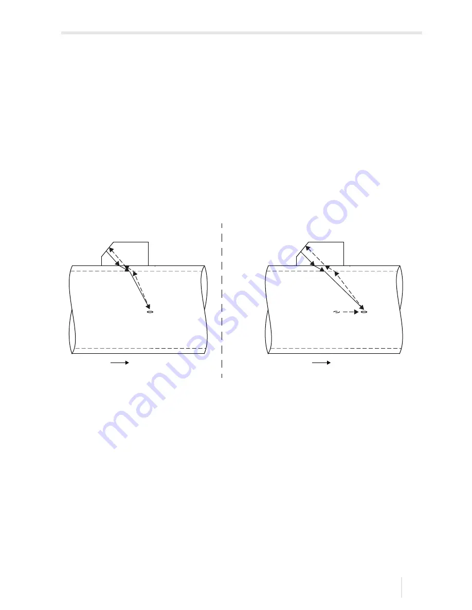
Measurement of the flow velocity in the NoiseTrek mode
If the proportion of gas or solids in the fluid is high, the damping of the ultrasonic signal
can be so high that the complete propagation of the fluid and therefore a measurement in
TransitTime mode is not possible anymore. In this case the NoiseTrek mode has to be
used.
The NoiseTrek mode uses the presence of gas bubbles and/or solids in the fluids.
Ultrasonic signals are sent from a transducer into the fluid at short intervals, reflected by
the gas bubbles and/or the solids particles and again received by the same transducer.
The measurement setup used in the TransitTime mode does not need to be changed.
The transit time difference
t of two consecutive ultrasonic signals is determined. It be-
haves proportionately to the distance the solid particle is covering between two consecu-
tive pulses and thus, to the average flow velocity of the fluid, see Fig. 3.4.
The average flow velocity of the fluid is calculated as follows:
v = k
Re
· k
a
·
where
Depending on the attenuation of the ultrasonic signal, the error of measurement in the
NoiseTrek mode can be greater than in the TransitTime mode.
Fig. 3.4:
Measurement of the flow velocity in the NoiseTrek mode
v
–
average flow velocity of the fluid
k
Re
–
fluid mechanics calibration factor
k
a
–
acoustic calibration factor
∆
t
p
–
time difference between 2 consecutive pulses
∆
t
–
transit time difference of ultrasonic signals S
1
and S
2
(
∆
t = t
2
- t
1
)
flow direction
transducer 1
transducer 1
flow direction
ultrasonic signal S
1
gas bubble or
solids particle
ultrasonic signal S
2
pulse at
time t
gas bubble or
solids particle
pulse at
time t +
∆
t
p
transit time t
1
transit time t
2
t
2
t
p
----------------