Festo CMMP-AS-***-M0 Series Manual Download Page 219

B

Diagnostic messages

Festo – GDCP-CMMP-M3/-M0-C-CO-EN – 1510b – English

219

B

Diagnostic messages

If an error occurs, the motor controller CMMP‐AS‐...‐M3/-M0 shows a diagnostic message cyclically in

the 7-segments display. An error message consists of an E (for Error), a main index and sub-index, 

e.g.: 

- E 0 1 0 -

.

Warnings have the same number as an error message. In contrast to error messages, however,

warnings are preceded and followed by hyphens, e.g. 

- 1 7 0 -

.

B.1

Explanations on the diagnostic messages

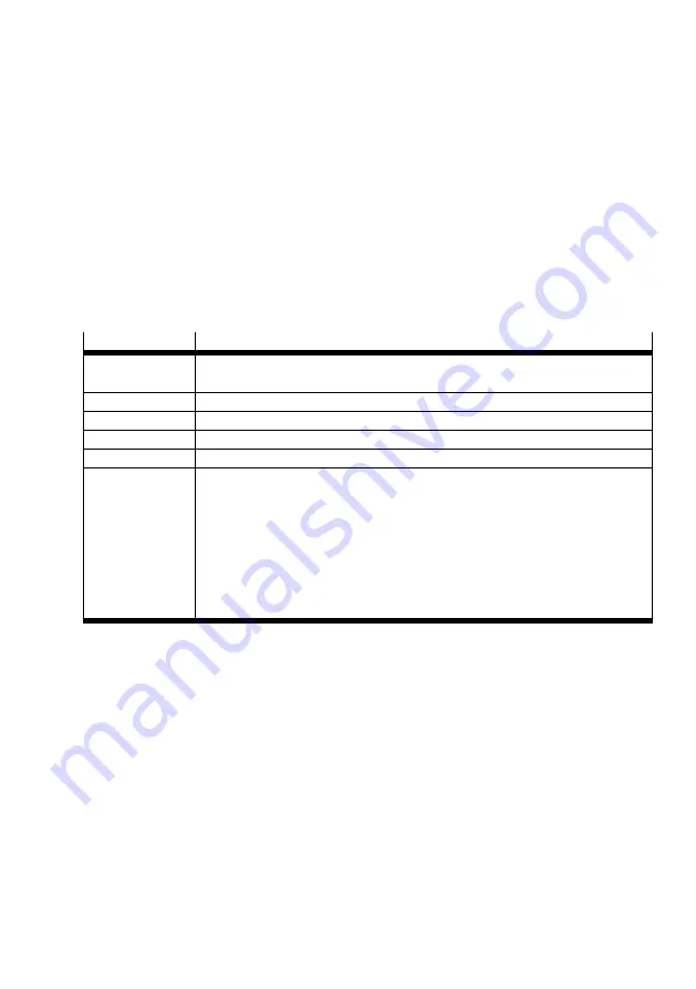
The following table summarises the significance of the diagnostic messages and the actions to be

taken in response to them:

Terms

Significance

No.

Main index (error group) and sub-index of the diagnostic message.

Shown in the display, in FCT or diagnostic memory via FHPP.

Code

The Code column includes the error code (Hex) via CiA 301.

Message

Message that is displayed in the FCT.

Cause

Possible causes for the message.

Action

Action by the user.

Reaction

The Reaction column includes the error response (default setting, partially

configurable):

PS off (switch off output stage),

MCStop (fast stop with maximum current),

QStop (fast stop with parameterised ramp),

Warn (warning),

Ignore (No message, only entry in diagnostic memory),

NoLog (No message and no entry in diagnostic memory).

Tab. B.1

Explanations of the diagnostic messages

Under section B.2, you will find the error codes in accordance with CiA301/402 with assignment to the

error numbers of the diagnostic messages.

A complete list of the diagnostic messages corresponding to the firmware statuses at the time of print­

ing of this document can be found in section B.3.

Summary of Contents for CMMP-AS-***-M0 Series

Page 1: ...vice profile CiA 402 for motor controller CMMP AS M3 via fieldbus CANopen EtherCAT with interface CAMC EC for motor controller CMMP AS M0 via fieldbus CANopen 8046795 1510b CMMP AS M3 M0 CiA 402 for motor controller ...

Page 2: ...eath or serious injuries Warning Hazards that can cause death or serious injuries Caution Hazards that can cause minor injuries or serious material damage Other symbols Note Material damage or loss of function Recommendations tips references to other documentation Essential or useful accessories Information on environmentally sound usage Text designations Activities that may be carried out in any ...

Page 3: ...ical units factor group 15 2 4 Configuration of CANopen participants on the CMMP AS M0 16 2 4 1 Setting the node number via DINs and FCT 17 2 4 2 Setting the transmission rate via DINs or FCT 17 2 4 3 Setting the protocol data profile via DINs or FCT 18 2 4 4 Activation of CANopen communication via DINs or FCT 18 2 4 5 Setting the physical units factor group 19 2 5 Configuration CANopen master 19 ...

Page 4: ...n allocation and cable specifications 48 4 5 Configuration of EtherCAT participants 50 4 5 1 Setting of the physical units of measure Factor Group 50 4 6 CANopen communication interface 51 4 6 1 Configuration of the Communication Interface 51 4 6 2 New and revised objects under CoE 54 4 6 3 Objects not supported under CoE 61 4 7 Communication Finite State Machine 62 4 7 1 Differences between the f...

Page 5: ... Device Control 150 6 1 Status Diagram State Machine 150 6 1 1 Overview 150 6 1 2 Status diagram of the motor controller state machine 151 6 1 3 Control word controlword 156 6 1 4 Read out of the motor controller status 159 6 1 5 Status words statuswords 160 6 1 6 Description of the additional objects 170 7 Operating modes 173 7 1 Setting the operating mode 173 7 1 1 Overview 173 7 1 2 Description...

Page 6: ... Speed ramps 209 7 7 Torque Regulation Operating Mode Profile Torque Mode 212 7 7 1 Overview 212 7 7 2 Description of the Objects 213 A Technical appendix 218 A 1 Technical Data Interface EtherCAT 218 A 1 1 General 218 A 1 2 Operating and environmental conditions 218 B Diagnostic messages 219 B 1 Explanations on the diagnostic messages 219 B 2 Error codes via CiA 301 402 220 B 3 Diagnostic message...

Page 7: ...n GDCP CMMP AS M3 HW or GDCP CMMP AS M0 HW see Tab 2 Target group This description is intended exclusively for technicians trained in control and automation technology who have experience in installation commissioning programming and diagnosing of positioning systems Service Please consult your regional Festo contact if you have any technical problems Information on the version This description re...

Page 8: ... M0 with fieldbuses CANopen Modbus TCP Description of CiA 402 DS 402 GDCP CMMP M3 M0 C CO Control and parameterisation of the motor controller via the device profile CiA 402 DS402 Motor controller CMMP AS M3 with the following fieldbuses CANopen and EtherCAT Motor controller CMMP AS M0 with fieldbus CANopen Description of CAM editor P BE CMMP CAM SW Cam disc function CAM of the motor controller CM...

Page 9: ...h the DIP switches S1 Fieldbus Interface Description CANopen X4 integrated Chapter 2 EtherCAT Interface CAMC EC Chapter 4 Tab 1 1 Fieldbus interfaces for CiA 402 M0 The motor controllers CMMP AS M0 are only equipped with the CANopen fieldbus interface and do not feature any slots for interfaces switches or safety modules 1 2 3 4 5 1 DIP switches S1 for fieldbus settings on the switch or safety mod...

Page 10: ... 207 is generally not necessary CiA Draft Standard 301 This book describes the fundamental design of the object directory of a CANopen device and access to it The statements of DS201 207 are also made concrete The elements of the object directory needed for the CMMP motor controller families and the related access methods are described in this manual Procurement of DS 301 is recommended but not un...

Page 11: ... 1 Pin assignment for CAN interface X4 CAN bus cabling When cabling the motor controller via the CAN bus you should unconditionally observe the following information and instructions to obtain a stable trouble free system If cabling is improperly done malfunctions can occur on the CAN bus during operation These can cause the motor controller to shut off with an error for safety reasons Termination...

Page 12: ...tors of the other pair are used together for CAN GND The cable screening is connected to the CAN shield connection at all nodes A table with the technical data of usable cables is located at the end of this chapter The use of adapters is not recommended for CAN bus cabling If this is unavoidable then metallic plug housings should be used to connect the cable screening To keep the disturbance coupl...

Page 13: ...of the fieldbus connection take place on both pages We recommend that parameterisation of the slave should be executed first Then the master should be configured We recommend the following procedure 1 Setting of the offset of the node number bit rate and activation of the bus communication via DIP switches The status of the DIP switches is read once at Power ON RESET The CMMP AS takes over changes...

Page 14: ...e in the Operating Parameters tab DIP switches Value Example ON OFF Value 1 1 0 ON 1 2 2 0 ON 2 3 4 0 OFF 0 4 8 0 ON 8 5 16 0 ON 16 Total 1 5 Offset 1 31 1 27 1 The value 0 for the offset is interpreted in connection with a base address 0 as node number 1 A node number greater than 31 must be set with the FCT Tab 2 3 Setting of the offset of the node number Setting the base address of the node num...

Page 15: ...unication can be activated Please note that the above mentioned parameters can only be revised when the protocol is deactivated CANopen communication DIP switch 8 Deactivated OFF Enabled ON Tab 2 5 Activation of CANopen communication Please observe that CANopen communication can only be activated after the parameter set the FCT project has been saved and a Reset carried out If another fieldbus int...

Page 16: ...lave should be executed first Then the master should be configured The CAN bus specific parameters can be set on two paths These paths are separated from one another and are accessed via the option Fieldbus parameterisation via DINs on the Application data page in the FCT The option Fieldbus parameterisation via DINs is active on delivery and after a reset to the factory settings Parameterisation ...

Page 17: ...e number 0 15 11 Tab 2 7 Setting the node number Setting the base address of the node number via FCT The base address of the node number can be set via FCT on the Fieldbus panel in the Operating parameters tab The resulting node number is dependent on the option Fieldbus parameterisation via DINs on the Application data page If this option is activated the node number is determined by adding the b...

Page 18: ...ab 2 9 Activating the protocol data profile Setting the protocol data profile via FCT The protocol is set via FCT on the Fieldbus page in the Operating parameters tab 2 4 4 Activation of CANopen communication via DINs or FCT When the node number transmission rate and protocol data profile have been set CANopen commu nication can be activated Activation of CANopen communication via DIN CANopen comm...

Page 19: ...p section 5 3 Parameterisation can be carried out via FCT or the fieldbus 2 5 Configuration CANopen master You can use an EDS file to configure the CANopen master The EDS file is included on the CD ROM supplied with the motor controller You will find the most current version under www festo com sp EDS files Description CMMP AS M3 eds Motor controller CMMP AS M3 with protocol CiA402 DS 402 CMMP AS ...

Page 20: ...trol system CMMP SDO Confirmation from the controller Control system CMMP PDO transmit PDO Data from controller Control system CMMP PDO receive PDO Fig 3 1 Access procedure As a rule the motor controller is parametrised and also controlled via SDO access In addition other types of messages so called communication objects which are sent either by the motor controller or the higher level controller ...

Page 21: ...sends the motor control ler a write command to modify a parameter in the object directory or a read command to read out a parameter For each command the host receives an answer that either contains the read out value or in the case of a write command serves as an acknowledgement For the motor controller to recognise that the command is meant for it the host must send the command with a specific id...

Page 22: ...4Fh 4Bh 43h Response identifier in case of error 80h Tab 3 3 SDO response task identifier EXAMPLE UINT8 INT8 Reading of Obj 6061_00h Return data 01h Writing of Obj 1401_02h Data EFh Command 40h 61h 60h 00h 2Fh 01h 14h 02h EFh Response 4Fh 61h 60h 00h 01h 60h 01h 14h 02h UINT16 INT16 Reading of Obj 6041_00h Return data 1234h Writing of Obj 6040_00h Data 03E8h Command 40h 41h 60h 00h 2Bh 40h 60h 00h...

Page 23: ...04 00 47h Overflow of an internal variable general error 06 07 00 10h Protocol error Length of the service parameter does not agree 06 07 00 12h Protocol error Length of the service parameter is too large 06 07 00 13h Protocol error Length of the service parameter is too small 06 09 00 11h The addressed subindex does not exist 06 09 00 30h The data exceed the range of values of the object 06 09 00...

Page 24: ...nse XXXX SU WWWW XXXX SU WWWW UINT32 INT32 16 bit data hex Command XXXX SU XXXX SU Response XXXX SU WWWWWWWW XXXX SU WWWWWWWW 32 bit data hex Note that the commands are entered as characters without any blanks Read error Write error Command XXXX SU XXXX SU WWWWWWWW1 Response FFFFFFFF FFFFFFFF 32 bit error code F3 F2 F1 F0 in accordance with chap 32 bit error code F3 F2 F1 F0 in accordance with cha...

Page 25: ...acity When a PDO is used the motor controller is parametrised at the start of the application in such a way that with every change in the statusword object a PDO containing the statusword object is deposited Instead of constantly requesting the host computer thus automatically receives a corresponding message as soon as the event occurs A distinction is made between the following types of PDOs Typ...

Page 26: ... only be written if bit 31 is simultaneously set The set bit 30 shows when the identifier is read that the object cannot be requested by a remote frame This bit is ignored during writing and is always set during reading number_of_mapped_objects This object specifies how many objects should be mapped into the corresponding PDO The following limitations must be observed A maximum of 4 objects can be...

Page 27: ...edure is established 1 The number of mapped objects is set to 0 2 The parameters first_mapped_object fourth_mapped_object may be described The overall length of all objects is not relevant in this time 3 The number of mapped objects is set to a value between 1 4 The length of all these objects must now not exceed 64 bits Value Significance Permitted with 01h F0h SYNC message The numerical value sp...

Page 28: ...ts 0 3 Parametrisation of objects that are to be mapped The above listed objects must be combined into a 32 bit value Index 6041h Sub index 00h Length 10h first_mapped_object 60410010h Index 6061h Sub index 00h Length 08h second_mapped_object 60610008h Index 60FDh Sub index 00h Length 20h third_mapped_object 60FD0020h 4 Parametrisation of number of objects The PDO should contain 3 objects number_o...

Page 29: ...rameter description of the first TPDO is explicitly listed The meaning can also be used for the other PDOs which are listed in table form in the following Index 1800h Name transmit_pdo_parameter_tpdo1 Object Code RECORD No of Elements 3 Sub Index 01h Description cob_id_used_by_pdo_tpdo1 Data Type UINT32 Access rw PDO Mapping no Units Value Range 181h 1FFh bit 30 and 31 may be set Default Value C00...

Page 30: ...ping no Units Value Range 0 4 Default Value Table Sub Index 01h Description first_mapped_object_tpdo1 Data Type UINT32 Access rw PDO Mapping no Units Value Range Default Value Table Sub Index 02h Description second_mapped_object_tpdo1 Data Type UINT32 Access rw PDO Mapping no Units Value Range Default Value Table Sub Index 03h Description third_mapped_object_tpdo1 Data Type UINT32 Access rw PDO Ma...

Page 31: ..._03h inhibit time 100 μs UINT16 rw 0000h 1A00h_00h number of mapped objects UINT8 rw 01h 1A00h_01h first mapped object UINT32 rw 60410010h 1A00h_02h second mapped object UINT32 rw 00000000h 1A00h_03h third mapped object UINT32 rw 00000000h 1A00h_04h fourth mapped object UINT32 rw 00000000h 2 Transmit PDO Index Comment Type Acc Default Value 1801h_00h number of entries UINT8 ro 03h 1801h_01h COB ID...

Page 32: ...entries UINT8 ro 03h 1803h_01h COB ID used by PDO UINT32 rw C0000481h 1803h_02h transmission type UINT8 rw FFh 1803h_03h inhibit time 100 μs UINT16 rw 0000h 1A03h_00h number of mapped objects UINT8 rw 02h 1A03h_01h first mapped object UINT32 rw 60410010h 1A03h_02h second mapped object UINT32 rw 606C0020h 1A03h_03h third mapped object UINT32 rw 00000000h 1A03h_04h fourth mapped object UINT32 rw 000...

Page 33: ... ro 02h 1400h_01h COB ID used by PDO UINT32 rw C0000201h 1400h_02h transmission type UINT8 rw FFh 1600h_00h number of mapped objects UINT8 rw 01h 1600h_01h first mapped object UINT32 rw 60400010h 1600h_02h second mapped object UINT32 rw 00000000h 1600h_03h third mapped object UINT32 rw 00000000h 1600h_04h fourth mapped object UINT32 rw 00000000h 2 Receive PDO Index Comment Type Acc Default Value 1...

Page 34: ... 1403h_01h COB ID used by PDO UINT32 rw C0000501h 1403h_02h transmission type UINT8 rw FFh 1603h_00h number of mapped objects UINT8 rw 02h 1603h_01h first mapped object UINT32 rw 60400010h 1603h_02h second mapped object UINT32 rw 60FF0020h 1603h_03h third mapped object UINT32 rw 00000000h 1603h_04h fourth mapped object UINT32 rw 00000000h 3 3 3 Activation of PDOs For the motor controller to send o...

Page 35: ...hronisation messages All connected controllers receive these messages and use them for treatment of the PDOs chapter 3 3 80h 0 Identifier Data length The identifier on which the motor controller receives the SYNC message is set permanently to 080h The identifier can be read via the object cob_id_sync Index 1005h Name cob_id_sync Object Code VAR Data Type UINT32 Access rw PDO Mapping no Units Value...

Page 36: ...GENCY message The identifier of this message is made up of the identifier 80h and the node number of the relevant controller 2 Error free Error occured 0 1 3 4 After a reset the controller is in the status Error free which it might leave again immediately because an error is on hand from the beginning The following status transitions are possible No Cause Significance 0 Initialisation completed 1 ...

Page 37: ... overtemperature 4 O communication error overrun error state 5 O 6 O reserved fix 0 7 O reserved fix 0 Values 0 no error 1 error present 1 M required O optional Tab 3 9 Bit assignment error_register The error codes as well as the cause and measures can be found in chapter B Diagnostic messages 3 5 3 Description of the Objects Object 1003h pre_defined_error_field The respective error_code of the er...

Page 38: ...tandard_error_field_0 Access ro PDO Mapping no Units Value Range Default Value Sub Index 02h Description standard_error_field_1 Access ro PDO Mapping no Units Value Range Default Value Sub Index 03h Description standard_error_field_2 Access ro PDO Mapping no Units Value Range Default Value Sub Index 04h Description standard_error_field_3 Access ro PDO Mapping no Units Value Range Default Value ...

Page 39: ...ressed simultaneously It is thus possible for example that a reset is triggered in all devices simultaneously The controllers do not acknowledge the NMT commands Successful comple tion can only be determined indirectly e g through the switch on message after a reset Structure of the NMT Message 000h 2 CS NI Identifier 000h Command specifier Data length Node ID For the NMT status of the CANopen nod...

Page 40: ...machine All other status transitions are performed automatically by the controller e g because the initialisation is completed In the NI parameter the node number of the controller must be specified or zero if all nodes in the net work are to be addressed broadcast Depending on the NMT status certain communication objects cannot be used For example it is absolutely necessary to place the NMT statu...

Page 41: ... incomplete defective parameter set The delay can be in the range of a few seconds The communication status must be set to operational for the controller to transmit and receive PDOs 3 7 Bootup 3 7 1 Overview After the power supply is switched on or after a reset the controller reports via a Bootup message that the initialisation phase is ended The controller is then in the NMT status preoperation...

Page 42: ...cols are activated simultaneously only the Heart beat protocol is active 3 8 2 Structure of the Heartbeat Message The Heartbeat telegram is transmitted with the identifier 700h node number It contains only 1 byte of user data the NMT status of the controller chapter 3 6 Network Management NMT Service 701h 1 N Identifier 700h node number NMT status Data length N Significance 04h Stopped 05h Operati...

Page 43: ...ways responds with the same toggle bit the master can react accordingly Likewise the drive monitors the regular arrival of the No deguarding requests from the master If messages are not received for a certain time period the con troller triggers error 12 4 Since both Heartbeat and Nodeguarding telegrams chapter 3 8 are sent with the identifier 700h node number both protocols cannot be active simul...

Page 44: ...erwise error 12 4 is triggered The toggle bit is reset through the NMT command Reset Communication It is therefore deleted in the first response of the controller 3 9 3 Description of the Objects Object 100Ch guard_time To activate the Nodeguarding monitoring the maximum time between two remote requests of the mas ter is parametrised This time is established in the controller from the product of g...

Page 45: ...s Value Range 0 1 Default Value 0 3 9 5 Table of Identifiers The following table gives an overview of the identifiers used Object type Identifier hexadecimal Comment SDO Host to controller 600h node number SDO Controller to host 580h node number TPDO1 180h Standard values Can be revised if needed TPDO2 280h TPDO3 380h TPDO4 480h RPDO1 200h RPDO2 300h RPDO3 400h RPDO4 500h SYNC 080h EMCY 080h node ...

Page 46: ...handled like a fieldbus thanks to high speed flexible topology line tree star and simple configuration The EtherCAT protocol is transported with a special standardised Ethernet type directly in the Ethernet frame in accordance with IEEE802 3 The slaves can broadcast multicast and communicate laterally For EtherCAT the data exchange is based on a pure hardware machine Abbreviation Significance ESC ...

Page 47: ...hronous setpoint value transfer LED displays for ready status and link detect Connection and display elements of the EtherCAT interface The following elements can be found on the front plate of the EtherCAT interface LED 1 two colour LED for EtherCAT communication yellow Connection active on Port 1 red Run green LED 2 red for displaying Connection active on Port 2 Two RJ45 sockets The following fi...

Page 48: ... or a previous station of a series connection e g multiple motor controllers X2 RJ45 socket underneath End of a series connection or connection of additional downstream stations Tab 4 2 Design of plug connectors X1 and X2 Pin Specification 1 Receiver signal RX Wire pair 3 2 Receiver signal RX Wire pair 3 3 Transmission signal TX Wire pair 2 4 Wire pair 1 5 Wire pair 1 6 Transmission signal TX Wire...

Page 49: ...the EtherCAT network you must unconditionally follow the advice in the relevant literature or the subsequent information and instructions in order to maintain a stable trouble free system If the system is not cabled properly EtherCAT bus malfunc tions can occur during operation These can cause the CMMP AS M3 motor controller to shut off with an error for safety reasons Bus termination No external ...

Page 50: ...erisation the application is ready immediately without communication faults We recommend the following procedure 1 Activation of the bus communication EtherCAT communication is automatically started through the CMMP AS M3 if it detects after switch on that an EtherCAT interface is plugged in Communication cannot be deactivated by flipping DIL switch 8 2 Parameterisation and commissioning with the ...

Page 51: ...plementation under EtherCAT which are required for special connection via CoE This is the result of the revised communication interface between the EtherCAT protocol and the CANopen protocol A so called Sync Manager is used to control the transmission of PDOs and SDOs via the two EtherCAT transfer types mailbox and process data protocol This Sync Manager and the necessary configuration steps for o...

Page 52: ...CAT protocol a so called Sync Manager is implemented under EtherCAT This Sync Manager is used to link the data of the PDOs and SDOs to be sent to the EtherCAT telegrams To accomplish this the Sync Manager provides multiple Sync channels which can each implement a CANopen data channel Receive SDO Transmit SDO Receive PDO or Transmit PDO on the EtherCAT telegram The figure shows how the Sync Manager...

Page 53: ...sation of the PDOs is carried out as described in chapter 3 CANopen access procedure The Sync channels can only be set and the PDOs only configured in the Pre Operational status It is not intended to parameterise the slave under EtherCAT The device description files are available for this purpose They prescribe the total parametrisation including PDO parametrisation which is used by the master dur...

Page 54: ...ng Identifier of the 4th Transmit PDO 1C00h Sync Manager Communication Type Object for configuring the individual Sync channels SDO or PDO Transfer 1C10h Sync Manager PDO Mapping for Sync Channel 0 Assignment of the Sync channel 0 to a PDO SDO Channel 0 is always reserved for Mailbox Receive SDO Transfer 1C11h Sync Manager PDO Mapping for Sync Channel 1 Assignment of the Sync channel 1 to a PDO SD...

Page 55: ...e various channels of the EtherCAT Sync Manager to be read As the CMMP AS M3 only supports the first four Sync channels under the EtherCAT CoE protocol the following objects are read only The Sync Manager for the CMMP AS M3 is configured as a result The objects have the following significance Index 1C00h Name Sync Manager Communication Type Object Code Array Data Type uint8 Sub Index 00h Descripti...

Page 56: ... Sync Channel 3 Access ro PDO Mapping no Value Range 0 unused 4 Process Data Input TxPDO Master Slave Default Value 4 Object 1C10h Sync Manager Channel 0 Mailbox Receive This object allows a PDO to be configured for Sync channel 0 As Sync channel 0 is always allocated to the mailbox telegram protocol the user cannot change this object The object therefore always has the following values Index 1C10...

Page 57: ... 00h Description Number of assigned PDOs Access ro PDO Mapping no Value Range 0 no PDO assigned to this channel Default Value 0 no PDO assigned to this channel Object 1C12h Sync Manager Channel 2 Process Data Output This object allows a PDO to be configured for Sync channel 2 Sync channel 2 is permanently assigned for the reception of Receive PDOs Master Slave In this object the number of PDOs ass...

Page 58: ...mber of assigned RxPDO Access rw PDO Mapping no Value Range 1600h first Receive PDO Default Value 1600h first Receive PDO Sub Index 02h Description PDO Mapping object Number of assigned RxPDO Access rw PDO Mapping no Value Range 1601h second Receive PDO Default Value 1601h second Receive PDO Sub Index 03h Description PDO Mapping object Number of assigned RxPDO Access rw PDO Mapping no Value Range ...

Page 59: ...o 1A03h Index 1C13h Name Sync Manager Channel 3 Process Data Input Object Code Array Data Type uint8 Sub Index 00h Description Number of assigned PDOs Access rw PDO Mapping no Value Range 0 no PDO assigned to this channel 1 one PDO assigned to this channel 2 two PDOs assigned to this channel 3 three PDOs assigned to this channel 4 four PDOs assigned to this channel Default Value 0 no PDO assigned ...

Page 60: ... object Number of assigned TxPDO Access rw PDO Mapping no Value Range 1A02h third Transmit PDO Default Value 1A02h third Transmit PDO Sub Index 04h Description PDO Mapping object Number of assigned TxPDO Access rw PDO Mapping no Value Range 1A03h fourth Transmit PDO Default Value 1A03h fourth Transmit PDO ...

Page 61: ...ndex Specifies the unit for displaying the position values in the controller The object is only available as a data container The firmware is not evaluated further 608Bh velocity_notation_index Specifies the number of decimal places for displaying the velocity values in the controller The object is only available as a data container The firmware is not evaluated further 608Ch velocity_dimension_in...

Page 62: ...ter This includes setting up the asynchronous communication between master and slave mailbox telegram protocol There is no direct communication between the master and slave yet The configuration starts saved values are loaded When all devices are con nected to the bus and configured the status switches to Pre Operational Pre Operational In this status asynchronous communication between the master ...

Page 63: ...Inputs Update start of cyclic communication process data telegram protocol Slave sends actual values to master The slave ignores setpoint values from the master and uses internal default values SP Stop Input Update stop of cyclic communication process data telegram protocol The slave no longer sends actual values to the master SO Start Output Update The slave evaluates up to date setpoint specific...

Page 64: ...n the EtherCAT finite state machine the Bootstrap status is also specified in addition to the statuses listed here This status is not implemented for the motor controller CMMP AS M3 4 7 1 Differences between the finite state machines of CANopen and EtherCAT When operating the CMMP AS M3 via the EtherCAT CoE protocol the EtherCAT finite state machine is used instead of the CANopen NMT finite state ...

Page 65: ...the motor controller CMMP AS M3 as only standard CANopen objects can be addressed The maximum size of these objects is 32 bits Tab 4 12 SDO Frame elements In order to transmit a standard CANopen object via one of these SDO frames the actual CANopen SDO frame is packaged in an EtherCAT SDO frame and transmitted Standard CANopen SDO frames can be used for Initialisation of the SDO download Download ...

Page 66: ...ct Process Data optional Optional data content of additional PDOs Tab 4 13 PDO Frame elements To transmit a PDO via the EtherCAT CoE protocol in addition to the PDO configuration PDO Mapping the Transmit and Receive PDOs must be assigned to a transmission channel of the Sync Manager chapter 4 6 1 Configuration of the Communication Interface The data exchange of PDOs for the motor controller CMMP A...

Page 67: ...3 also supports the Sync Message transmission type However the Sync Message does not have to be sent via EtherCAT It is used either for the arrival of the telegram or the hardware synchronisation pulse of the Distributed Clocks mechanism see below for data transfer The EtherCAT interface for CMMP AS M3 supports synchronisation via the Distributed Clocks mechanism specified under EtherCAT by means ...

Page 68: ...ter and slaves exchange error messages via the EtherCAT CoE emergency frame The CoE emer gency frames are used for direct transfer of the Emergency Messages defined under CANopen The CANopen telegrams are simply tunnelled through the CoE emergency frames as is the case for SDO and PDO transmission 6 bytes 2 bytes 1 byte 2 bytes 5 bytes 1 n bytes Mandatory Header Standard CANopen Emergency Frame Op...

Page 69: ...an be changed using this file Festo has created a device description file for the CMMP AS M3 motor controller It can be down loaded from the Festo homepage Its contents will now be described in more detail to permit users to adapt this file to their application The available device description file supports both the CiA 402 profile and the FHPP profile via separ ately selectable modules The XML fi...

Page 70: ...owing sub items Node name Significance Adaptable Vendor This node contains the name and the ID of the manufacturer of the device to which this description file belongs It also contains the binary code of a bitmap with the manufacturer s logo No Description This sub item contains the actual device description including the configuration and initialisation Partially Group This node contains the assi...

Page 71: ... detail in the following chapters The remaining content of the device description file is fixed and may not be changed by the user Important If changes are made to nodes and content other than the RxPDO TxPDO and Mailbox nodes in the device description file error free operation of the device can no longer be guaranteed 4 12 2 Receive PDO configuration in the RxPDO node The RxPDO node is used to sp...

Page 72: ...utput for a Receive PDO No Entry Each Entry node contains a CANopen object to be mapped to the PDO An Entry node contains the index and sub index of the CANopen object to be mapped as well as their name and data type Yes Tab 4 18 Elements of the node RxPDO The sequence and mapping of the individual CANopen objects for the PDO correspond to the sequence in which they are specified via the Entry ent...

Page 73: ...and sub index as well as the data value to be written and comments A typical entry has the following form InitCmd Transition PS Transition Index x6060 Index SubIndex 0 SubIndex Data 03 Data Comment velocity mode Comment InitCmd In the example above status transition PS from Pre Operational to Safe Operational sets the oper ating mode in the CANopen object modes_of_operation to Speed adjustment The...

Page 74: ...ion The cycle time of the EtherCAT Frame must exactly match the cycle time tp of the controller internal interpolator If necessary the interpolator time must be ad justed via the object included in the device description file In the present implementation synchronous transfer of PDO data and synchronisation of the controller internal PLL to the synchronous data framework of the EtherCAT Frame can ...

Page 75: ...cation with a motor controller CMMP AS M3 M0 in a sensible way If required read about this in the specifications of CiA 5 1 Loading and Saving Parameter Sets Overview The motor controller has three parameter sets Current parameter set This parameter set is located in the volatile memory RAM of the motor controller It can be read and written on as desired with the parametrisation software or via th...

Page 76: ...is based on the fact that most application specific parameter sets deviate from the default parameter set in only a few parameters This makes it possible for the current parameter set to be newly constructed via the CAN bus each time the system is switched on To do this the higher level controller first loads the default parameter set call up of the CANopen object 1011h_01h restore_all_default_par...

Page 77: ...eter set The copying process is triggered by a write access to this object whereby the string load must be transferred as a record in hexadecimal form This command is only carried out with a deactivated output stage Otherwise the SDO error Data cannot be transmitted or stored since the motor controller for this is not in the correct state is gener ated If the incorrect identifier is sent the error...

Page 78: ...ot reflect the end of the storage procedure But this behaviour can be revised through the object 6510h_F0h compatibility_control 5 2 Compatibility settings Overview In order to remain compatible with earlier CANopen implementations e g also in other device families and still be able to execute changes and corrections compared to CiA 402 and CiA 301 the object com patibility_control was introduced ...

Page 79: ... to save_all_parameters is not sent until saving is completed This can take several seconds which might result in a time out in the controller If the bit is deleted answering takes place immediately but it should be considered that the saving procedure has not been completed yet 5 0020h Reserved The bit is reserved It must not be set 6 0040h homing_to_zero Up to now homing under CANopen consists o...

Page 80: ...signated position_units speed_units or acceleration_units The following sketch illustrates the function of the factor group Position Factor Item Factor group User units Internal controller units Position units Velocity units 1 position_polarity_flag Acceleration units 1 Velocity factor Speed 1 velocity_polarity_flag 1 Acceleration factor Acceleration Increments Inc 1 Revolution 4096 min 1 Revoluti...

Page 81: ...ctor UINT32 rw Object 6093h position_factor The object position_factor converts all units of length of the application from position_units into the internal unit increments 65536 increments correspond to 1 revolution It consists of numerator and denominator Motor Gear unit Axis Motor with gearing RIN ROUT x in positioning unit e g mm x in positioning unit e g degrees Fig 5 3 Calculating the positi...

Page 82: ...tions at the drive in RIN and revolutions at the drive out ROUT feed_constant Ratio between revolutions at the drive out ROUT and movement in posi tion_units e g 1 R 360 degrees Tab 5 4 Position factor parameters The position_factors is calculated using the following formula position_factor numerator divisor Gear ratio IncrementsńRevolution Feed constant The position_factor must be written to the ...

Page 83: ...ulating the position factor Position units1 Feed constant2 Gear ratio3 Formula4 Result shortened Increments 0 DP Inc 1 ROUT 65536 Ink 1 1 1 1 65536 Inc 65536 Inc 1 Inc 1 Inc num 1 div 1 Degree 1 DP 1 10 degree 10 1 ROUT 3600 10 1 1 1 1 65536 Inc 3600 10 65536 Inc 3600 10 num 4096 div 225 Rev 2 DP 1 100 Rev R 100 1 ROUT 100 R 100 1 1 1 1 65536 Inc 100 1 100 65536 Inc 100 1 100 num 16384 div 25 2 3 ...

Page 84: ...1 Calculation of the velocity_encoder_factor is in principle made up of two parts a conversion factor from internal length units into position_units and a conversion factor from internal time units into user defined time units e g from seconds into minutes The first part corresponds to the calculation of the position_factor for the second part an additional factor is added to the calculation Param...

Page 85: ... unit column 1 and the desired number of decimal places dp have to be specified along with the application s gear ratio and its feed constant if applicable The feed constant is then displayed in the desired positioning units column 2 Then the desired time unit is converted into the time unit of the motor controller column 3 Finally all values can be entered into the formula and the fraction can be...

Page 86: ...5 mm s 1 DP 1 10 mm s mm 10 s 63 15 mm R å 1 ROUT 631 5 mm 10 1 1 s 60 1 min 60 4096 1 4096 min 4 5 4 5 60 4096 1 4096min 1 1 s 631 5 mm 10 1 1966080 1 4096min 6315 mm 10 s num 131072 div 421 1 Desired unit at the drive out 2 Positioning units per revolution at the drive out ROUT Feed constant of the drive 10 DP points after the decimal 3 Time factor_v desired time unit per internal time unit 4 Ge...

Page 87: ...osition_factor for the second part an additional factor is added Parameters Description time_factor_a The ratio between the internal time unit squared and the user defined time unit squared e g 1 min2 1 min x 1 min 60 s x 1 min 60 256 256 min x s gear_ratio Gear ratio between revolutions at the input shaft RIN and revolutions at the output shaft ROUT feed_constant Ratio between revolutions at the ...

Page 88: ...ts of acceleration1 Feed const 2 Time Constant3 Gear 4 Formula5 Result shortened R min 0 DP R min s 1 ROUT 1 ROUT 1 1 min s 256 1 min 256 s 1 1 1 1 256 1 256 min s 1 1 min s 1 1 256 1 min 256 s 1 1 min s num 256 div 1 s 1 DP 1 10 s 10 s 1 ROUT 3600 10 1 1 s2 60 1 min s 60 256 1 min 256 s 1 1 1 1 60 256 1 256 min s 1 1 s2 3600 10 1 15360 1 min 256 s 3600 10 s2 num 64 div 15 R min 2 DP 1 100 R min R...

Page 89: ...e to set the position_polarity_flag and the velocity_polarity_flag to the same value Setting of the polarity_flag influences only parameters when reading and writing Parameters already present in the motor controller are not changed Index 607Eh Name polarity Object Code VAR Data Type UINT8 Access rw PDO mapping yes Units Value Range 40h 80h C0h Default Value 0 Bit Value Name Meaning 6 40h velocity...

Page 90: ...ould also be able to interrupt them in case of a defective microprocessor The removal of the output stage enable with running motor thus ensures that the motor runs out unbraked or is only stopped by the holding brake if on hand The controller enable is processed by the microcon troller of the motor controller Depending on the operating mode the motor controller reacts differently after removal of...

Page 91: ...ut stage enable controller enable CAN Object 6510h_30h pwm_frequency The switching losses of the output stage are proportional to the switching frequency of the power transistors With the devices of the CMMP family cutting the normal pulse width modulation frequency in half can produce more output But the current ripple factor caused by the output stage rises Reversing is only possible when the ou...

Page 92: ...rformed Sub Index 3Ah Description enable_enhanced_modulation Data Type UINT16 Access rw PDO mapping no Units Value Range 0 1 Default Value 0 Value Meaning 0 Extended sine modulation OFF 1 Extended sine modulation ON Activation of the extended sine modulation is only effective after a reset As a result the parameter set must be saved save_all_parameters and then a reset performed Object 6510h_31h p...

Page 93: ... Value Range 100 Default Value device dependent Object 6510h_33h nominal_dc_link_circuit_voltage Through the object nominal_dc_link_circuit_voltage the nominal device voltage can be read in milli volt Sub Index 33h Description nominal_dc_link_circuit_voltage Data Type UINT32 Access ro PDO mapping no Units mV Value Range Default Value device dependent Object 6510h_34h actual_dc_link_circuit_voltage...

Page 94: ..._voltage specifies up to which lower intermediate circuit voltage the motor controller should work Below this voltage the error E 02 0 is triggered if it was activated with the subsequent object Sub Index 36h Description min_dc_link_circuit_voltage Data Type UINT32 Access rw PDO mapping no Units mV Value Range 0 1000000 Default Value 0 Object 6510h_37h enable_dc_link_undervoltage_error The undervo...

Page 95: ...ndex 40h Description nominal_current Data Type UINT32 Access ro PDO mapping no Units mA Value Range Default Value device dependent Other values may be displayed due to a power derating dependent on the controller cycle time and the output stage clock frequency Object 6510h_41h peak_current The device peak current can be read with the object peak_current It is simultaneously the upper limit value w...

Page 96: ...the phase sequence in the motor and angle transmitter cable Offset Angle Dependent on the motor and on the phase sequence in the motor and angle transmitter cable Please observe that the direction of rotation and offset angle also depend on the cable set used The parameter sets therefore work only with identical cabling Caution If the phase sequence is distorted in the motor or angle encoder cable...

Page 97: ... always be parametrised again Object 6073h max_current As a rule servo motors may be overloaded for a certain time period With this object the maximum permissible motor current is set as a factor It refers to the nominal motor current object 6075h mo tor_rated_current and is set in thousandths The range of values is limited upward by the maximum controller current object 6510h_41h peak_current Man...

Page 98: ...DO mapping yes Units Value Range 2 254 Default Value 4 after INIT Object 6410h_03h iit_time_motor As a rule servo motors may be overloaded for a certain time period This object specifies how long current can flow through the connected motor with the current specified in the object 6073h max_current After expiration of the I2t time to protect the motor the current is automatically limited to the va...

Page 99: ...2t limitation oc curs Either it is only displayed in the status word or error E 31 0 is triggered Index 6510h Name drive_data Object Code RECORD No of Elements 51 Sub Index 38h Description iit_error_enable Data Type UINT16 Access rw PDO mapping no Units Value Range 0 1 Default Value 0 Value Meaning 0 I2t error OFF Priority WARNING 1 I2t error ON Priority CONTROLLER ENABLE OFF The error E 31 0 is a...

Page 100: ...ust always set the electromagnetic field of the stator in the correct angle to this permanent magnet field To do this it constantly determines the rotor position with an angle encoder resolver etc The orientation of the angle encoder to the permanent magnetic field must be entered in the object resolver_offset_angle This angle can be determined with the parametrisation software The angle de termin...

Page 101: ...re With this object the current motor temperature can be read if an analogue temperature sensor is con nected Otherwise the object is undefined Index 6510h Name drive_data Object Code RECORD No of Elements 51 Sub Index 2Eh Description motor_temperature Data Type INT16 Access ro PDO mapping yes Units C Value Range Default Value Object 6510h_2Fh max_motor_temperature If the motor temperature defined...

Page 102: ...0h must be written in the object torque_control_gain The current controller time constant is specified in the parametrisation software in milliseconds To transfer this time constant into the object torque_control_time it must previously be converted into microseconds With a specified time of 0 6 milliseconds the corresponding value 600 is entered in the object torque_control_time Index 60F6h Name ...

Page 103: ... The data of the speed controller must be taken from the parametrisation software The following calcu lations must be observed Amplification of the speed regulator must be multiplied by 256 With an amplification of 1 5 in the Speed Regulator menu of the parametrisation software the value 384 180h must be written in the object velocity_control_gain The speed regulator time constant is specified in ...

Page 104: ... 32000 Default Value 400 Object 2073h velocity_display_filter_time The filter time constant of the display speed actual value filter can be set via the object velocity_display_filter_time Index 2073h Name velocity_display_filter_time Object Code VAR Data Type UINT32 Access rw PDO mapping no Units μs Value Range 1000 50000 Default Value 20000 Please observe that the object velocity_actual_value_fil...

Page 105: ...s the speed setpoint value All input and output variables of the position controller are converted in the Factor Group from the application specific units into the respective internal units of the regulator The following subfunctions are defined in this chapter 1 Contouring error Following_Error The deviation of the actual position value position_actual_ value from the position setpoint value posi...

Page 106: ...the objects Objects treated in this chapter Index Object Name Type Attr 202Dh VAR position_demand_sync_value INT32 ro 2030h VAR set_position_absolute INT32 wo 6062h VAR position_demand_value INT32 ro 6063h VAR position_actual_value_s1 INT32 ro 6064h VAR position_actual_value INT32 ro 6065h VAR following_error_window UINT32 rw 6066h VAR following_error_time_out UINT16 rw 6067h VAR position_window U...

Page 107: ...ion controller is relatively slow compared to the current and speed regulator Therefore the controller works internally with activation so the stabilisation work for the position controller is minim ised and the controller can rapidly stabilise A proportional link normally suffices as position controller Amplification of the position controller must be multiplied by 256 With an amplification of 1 ...

Page 108: ...84 Default Value 102 Sub Index 02h Description position_control_time Data Type UINT16 Access ro PDO mapping no Units μs Value Range 0 Default Value 0 Sub Index 04h Description position_control_v_max Data Type UINT32 Access rw PDO mapping no Units speed units Value Range 0 131072 min 1 Default Value 500 min 1 Sub Index 05h Description position_error_tolerance_window Data Type UINT32 Access rw PDO m...

Page 109: ... Elements INT32 Access ro PDO mapping yes Units position units Value Range Default Value Object 202Dh position_demand_sync_value The target position of the synchronisation encoder can be read out via this object This is defined through the object 2022h synchronization_encoder_select chap 5 11 This object is specified in user defined increments Index 202Dh Name position_demand_sync_value Object Cod...

Page 110: ...pecified in user defined increments Index 6064h Name position_actual_value Object Code VAR Data Type INT32 Access ro PDO mapping yes Units position units Value Range Default Value Object 6065h following_error_window The object following_error_window contouring error window defines a symmetrical range around the position setpoint value position_demand_value If the actual position value position_act...

Page 111: ...object occurs the related bit 13 following_error is set in the statusword Index 6066h Name following_error_time_out Object Code VAR Data Type UINT16 Access rw PDO mapping yes Units ms Value Range 0 27314 Default Value 0 Object 60F4h following_error_actual_value The current contouring error can be read out via this object This object is specified in user defined increments Index 60F4h Name followin...

Page 112: ...ess ro PDO mapping yes Units speed units Value Range Default Value Object 6067h position_window With the object position_window a symmetrical area is defined around the target position target_position If the actual position value position_actual_value lies within this area for a certain time the target position target_position is considered reached Index 6067h Name position_window Object Code VAR ...

Page 113: ...ded the output stage is immediately switched off and an error triggered The motor thus runs out unbraked unless a holding brake is on hand Index 6510h Name drive_data Object Code RECORD No of Elements 51 Sub Index 22h Description position_error_switch_off_limit Data Type UINT32 Access rw PDO mapping no Units position units Value Range 0 232 1 Default Value 0 Value Meaning 0 Contouring error limit ...

Page 114: ...Index 607Bh Name position_range_limit Object Code ARRAY No of Elements 2 Data Type INT32 Sub Index 01h Description min_position_range_limit Access rw PDO mapping yes Units position units Value Range Default Value Sub Index 02h Description max_position_range_limit Access rw PDO mapping yes Units position units Value Range Default Value Object 6510h_20h position_range_limit_enable Through the object...

Page 115: ...sition_absolute Through the object set_position_absolute the readable actual position can be displaced without chan ging the physical position The drive does not make any movement If an absolute encoder system is connected the position shift is stored in the encoder if the encoder system permits it The position shift thus remains intact even after a reset This storage operation runs in the backgro...

Page 116: ...rent_input_channel Here a choice can be made between specification of a direct setpoint value fixed value or specification via an analogue input Depending on the source chosen either the limit torque source fixed value or the scaling factor for the analogue inputs source analogue input is specified via the object limit_current In the first case the torque proportional current in mA is limited dire...

Page 117: ...etpoint value fixed value or specification via an analogue input Depending on the source chosen either the limit torque fixed value or the scaling factor for the analogue inputs source analogue input is specified via the object limit_speed In the first case the limit is at the specified speed in the second case the speed is specified that should correspond to a present voltage of 10 V Index 2416h ...

Page 118: ...this chapter Index Object Name Type Attr 2024h RECORD encoder_x2a_data_field ro 2024h_01h VAR encoder_x2a_resolution UINT32 ro 2024h_02h VAR encoder_x2a_numerator INT16 rw 2024h_03h VAR encoder_x2a_divisor INT16 rw 2025h RECORD encoder_x10_data_field ro 2025h_01h VAR encoder_x10_resolution UINT32 rw 2025h_02h VAR encoder_x10_numerator INT16 rw 2025h_03h VAR encoder_x10_divisor INT16 rw 2025h_04h V...

Page 119: ...Since only resolvers that are always evaluated using 16 bit can be connec ted at the input X2A 65536 is always returned here With the object encoder_x2a_numerator and encoder_x2a_divisor a gear unit also with prefix if necessary between motor shaft and encoder can be taken into account Index 2024h Name encoder_x2a_data_field Object Code RECORD No of Elements 3 Sub Index 01h Description encoder_x2a...

Page 120: ...0 and the set increment number 1 With the objects encoder_x2b_numerator and encoder_x2b_divisor a gear unit connected between the motor shaft and the encoder connected to X2B can be taken into account Index 2026h Name encoder_x2b_data_field Object Code RECORD No of Elements 4 Sub Index 01h Description encoder_x2b_resolution Data Type UINT32 Access rw PDO mapping no Units Increments 4 number of lin...

Page 121: ...e specified in the object encoder_X10_resolution This corresponds to four times the number of lines The object encoder_X10_counter supplies the currently counted incremental number between 0 and the set in crement number 1 With the object encoder_X10_numerator and encoder_X10_divisor a gear unit also with prefix if necessary between motor shaft and encoder can be taken into account With use of the...

Page 122: ...rements 4 number of lines Value Range 0 encoder_x10_resolution 1 Default Value 5 10 Incremental Encoder Emulation Overview This object group makes it possible to parametrise the incremental encoder output X11 As a result master slave applications in which the output of the master X11 is connected to the input of the slave X10 can hereby be parametrised under CANopen Description of the objects Obje...

Page 123: ...com pared to the zero position of the actual value encoder Index 201Ah Name encoder_emulation_data Object Code RECORD No of Elements 2 Sub Index 01h Description encoder_emulation_resolution Data Type INT32 Access rw PDO mapping no Units 4 number of lines Value Range 4 1 8192 Default Value 4096 Sub Index 02h Description encoder_emulation_offset Data Type INT16 Access rw PDO mapping no Units 32767 1...

Page 124: ...h VAR position_encoder_selection INT16 rw 2022h VAR synchronisation_encoder_selection INT16 rw 2023h VAR synchronisation_filter_time UINT32 rw 202Fh RECORD synchronisation_selector_data ro 202Fh_07h VAR synchronisation_main UINT16 rw Object 2021h position_encoder_selection The object position_encoder_selection specifies the encoder input that is used for regulation of the actual position actual po...

Page 125: ...nput As a result selection can be made between X10 and no input The same input should not be selected as synchronisation setpoint as for the actual value encoder Index 2022h Name synchronisation_encoder_selection Object Code VAR Data Type INT16 Access rw PDO mapping no Units Value Range 1 2 table Default Value 2 Value Measurement file 1 No encoder undefined 2 X10 Object 202Fh synchronisation_selec...

Page 126: ...ronisation during homing Object 2023h synchronisation_filter_time Through the object synchronisation_filter_time the filter time constant of a PT1 filter is established with which the synchronisation speed is smoothed This can be necessary especially with a low number of lines since even small changes in the input value here can correspond to high speeds On the other hand the drive might no longer...

Page 127: ...cription of the objects Index Object Name Type Attr 2400h ARRAY analog_input_voltage INT16 ro 2401h ARRAY analog_input_offset INT32 rw 2400h analog_input_voltage input voltage The object group analog_input_voltage delivers the current input voltage of the respective channel in millivolts taking into account the offset Index 2400h Name analog_input_voltage Object Code ARRAY No of Elements 3 Data Ty...

Page 128: ...et direct voltage that may be present can be compensated A positive offset compensates thereby for a positive input voltage Index 2401h Name analog_input_offset Object Code ARRAY No of Elements 3 Data Type INT32 Sub Index 01h Description analog_input_offset_ch_0 Access rw PDO mapping no Units mV Value Range 10000 10000 Default Value 0 Sub Index 02h Description analog_input_offset_ch_1 Access rw PD...

Page 129: ...l_output_state_mapping ro 2420h_01h VAR dig_out_state_mapp_dout_1 UINT8 rw 2420h_02h VAR dig_out_state_mapp_dout_2 UINT8 rw 2420h_03h VAR dig_out_state_mapp_dout_3 UINT8 rw Object 60FDh digital_inputs The digital inputs can be read via the object 60FDh Index 60Fdh Name digital_inputs Object Code VAR Data Type UINT32 Access ro PDO mapping yes Units Value Range according to the following table Defau...

Page 130: ...ack the object 60FEh Index 60FEh Name digital_outputs Object Code ARRAY No of Elements 2 Data Type UINT32 Sub Index 01h Description digital_outputs_data Access rw PDO mapping yes Units Value Range Default Value dependent on the status of the brake Sub Index 02h Description digital_outputs_mask Access rw PDO mapping yes Units Value Range Default Value 00000000h Bit Value Meaning 0 00000001h 1 Energ...

Page 131: ...ction has been assigned to a digital output and the output is then switched on or off dir ectly over digital_outputs 60FEh the object digital_outputs_state_mapping is also set to OFF 0 or ON 12 Index 2420h Name digital_outputs_state_mapping Object Code RECORD No of Elements 5 Sub Index 01h Description dig_out_state_mapp_dout_1 Data Type UINT8 Access rw PDO mapping no Units Value Range 0 44 table D...

Page 132: ...ition Trigger 3 21 Position Trigger 4 22 25 Reserved 26 Alternative target reached 27 Active if position set running 28 Declared torque reached 29 Position x_set x_target also with linking for at least 10 ms 30 Ack signal active low as handshake to start position 31 Destination reached with handshake for the dig Start is not set as long as START is on HIGH level 32 Cam disc active 33 CAM IN moveme...

Page 133: ...00FF0000h EA88_0_dout_2_mapping Function for CAMC D 8E8A 0 DOUT3 24 31 FF000000h EA88_0_dout_3_mapping Function for CAMC D 8E8A 0 DOUT4 Sub Index 12h Description dig_out_state_mapp_ea88_0_low Data Type UINT32 Access rw PDO mapping no Units Value Range 0 FFFFFFFFh table Default Value 0 Bit Mask Name Measurement file 0 7 000000FFh EA88_0_dout_4_mapping Function for CAMC D 8E8A 0 DOUT5 8 15 0000FF00h...

Page 134: ...ode Description of the objects Index Object Name Type Attr 6510h RECORD drive_data rw Object 6510h_11h limit_switch_polarity The polarity of the limit switches can be programmed via the object 6510h_11h limit_switch_polarity For normally closed limit switches a 0 must be entered in this object whereas a 1 must be entered when normally open contacts are used Index 6510h Name drive_data Object Code ...

Page 135: ...ng no Units Value Range 0 1 Default Value 0 Value Meaning 0 DIN6 E0 limit switch negative DIN7 E1 limit switch positive 1 DIN6 E1 limit switch positive DIN7 E0 limit switch negative Object 6510h_14h homing_switch_polarity The polarity of the reference switch can be programmed through the object 6510h_14h homing_switch_polarity For a normally closed reference switch a zero is entered in this object...

Page 136: ... Access rw PDO mapping no Units Value Range 0 1 Default Value 0 Value Meaning 0 DIN 9 1 DIN 8 Object 6510h_15h limit_switch_deceleration The object limit_switch_deceleration establishes the deceleration used in braking when the limit switch is reached during normal operation limit switch emergency stop ramp Sub Index 15h Description limit_switch_deceleration Data Type INT32 Access rw PDO mapping n...

Page 137: ... and the stamped positions can ulti mately be read via the objects sample_position_rising_edge and sample_position_falling_edge Which digital input is used can be established with the parametrisation software under Controller I O configuration Digital inputs Sample input Description of the objects Objects treated in this chapter Index Object Name Type Attr 204Ah RECORD sample_data ro 204Ah_01h VAR...

Page 138: ...e Description 0 01h falling_edge_occurred 1 New sample position falling edge 1 02h rising_edge_occurred 1 New sample position rising edge The bits of the object sample_status can be established with the following object which should also result in setting bit 15 of the status word Through this the information sample event occurred is available in the status word which will normally be transmitted ...

Page 139: ... sampling Sub Index 04h Description sample_control Data Type UINT8 Access wo PDO mapping yes Units Value Range 0 1 table Default Value 0 Bit Value Name Description 0 01h falling_edge_enable Sampling with falling edge 1 02h rising_edge_enable Sampling with rising edge The following objects contain the sampled positions Sub Index 05h Description sample_position_rising_edge Data Type INT32 Access ro ...

Page 140: ...e object brake_delay_time As can be seen from the sketch when the controller enable is switched on the speed setpoint value is approved only after the brake_delay_time and when the the controller enable is switched off turning off the regulation is delayed by this time Controller enable Holding brake released Actual speed value Internal controller enable Speed setpoint value 0 0 0 0 0 1 1 1 tF tF ...

Page 141: ... be read out of the device Description of the objects Object 1018h identity_object Through the identity_object established in the CiA 301 the motor controller can be uniquely identified in a CANopen network For this purpose the manufacturer code vendor_id a unique product code product_code the revision number of the CANopen implementation revision_number and the serial number of the device serial_...

Page 142: ...o PDO mapping no Units Value Range Default Value device dependent Sub Index 03h Description revision_number Data Type UINT32 Access ro PDO mapping no Units MMMMSSSSh M main version S sub version Value Range Default Value Sub Index 04h Description serial_number Data Type UINT32 Access ro PDO mapping no Units Value Range Default Value ...

Page 143: ...lue Object 6510h_A1h drive_type Through the object drive_type the device type of the controller can be read This object serves to achieve compatibility with earlier versions Sub Index A1h Description drive_type Data Type UINT32 Access ro PDO mapping no Units Value Range 1018h_02h product_code Default Value 1018h_02h product_code Object 6510h_A9h firmware_main_version The main version number of the...

Page 144: ... Value Object 6510h_ADh km_release Through the version number of the km_release firmware statuses of the same product stage can be differentiated Sub Index ADh Description km_release Data Type UINT32 Access ro PDO mapping no Units Value Range MMMMSSSSh M main version S sub version Default Value Object 6510h_ACh firmware_type Through the object firmware_type can be read for which device family and ...

Page 145: ...cletime_velocity_controller Through the object cycletime_velocity_controller the cycle time of the speed regulator in micro seconds can be read Sub Index B1h Description cycletime_velocity_controller Data Type UINT32 Access ro PDO mapping no Units μs Value Range Default Value 000000FAh Object 6510h_B2h cycletime_position_controller Through the object cycletime_position_controller the cycle time of...

Page 146: ...have been executed e g nominal current After delivery and after restore_default_parameter this object includes a 0 In this case an A is displayed on the 7 segments display of the motor con troller to point out that this device has not been parameterised yet If the motor controller is paramet erised completely under CANopen at least one bit in this object must be set to suppress the display A Of co...

Page 147: ...ic units valid 11 Speed regulator valid 12 Position controller valid 13 Safety parameters valid 14 Reserved 15 Limit switch polarity valid 16 31 Reserved Caution This object contains no information about whether the motor controller has been cor respondingly parametrised correctly for the motor and application but only whether the named points after shipment have been parametrised at all at least ...

Page 148: ...r from possible destruction If a lower error response is entered than is permissible for the respective error the value is limited to the lowest permissible error response A list of all error numbers is found in chapter B Diagnostic messages Description of the objects Objects treated in this chapter Index Object Name Type Attr 2100h RECORD error_management ro 2100_01h VAR error_number UINT8 rw 210...

Page 149: ...atus word 5 Controller enable off 7 Braking with maximum current 8 Output stage off Object 200Fh last_warning_code Warnings are special events of the drive e g a following error which in contrast to an error should not result in stopping of the drive Warnings are displayed on the 7 segments display of the controller and after that automatically reset by the controller The last warning that occurre...

Page 150: ... whether the output stage is switched on or an error has occurred for example The statuses defined under CANopen are presented in the course of the chapter Example SWITCH_ON_DISABLED Status transition state transition Just as with the statuses it is also defined under CANopen how to go from one status to another e g to acknowledge an error Status transitions are triggered by the host by setting bi...

Page 151: ...r state machine SWITCH_ON_DISABLED READY_TO_SWITCH_ON FAULT_REACTION_ACTIVE FAULT SWITCH_ON OPERATION_ENABLE QUICK_STOP_ACTIVE NOT_READY_TO_SWITCH_ON 1 0 0 2 7 aJ 3 6 8 9 aC aD aE aB aA Power enabled output stage on Fault error Power disabled output stage off 4 5 Fig 6 1 Status diagram of the motor controller ...

Page 152: ...status the system ultimately branches into the FAULT status Depending on the severity of the error certain actions such as emergency braking can still be per formed before FAULT_REACTION_ACTIVE In order to perform the named status transitions certain bit combinations must be set in the control word see below The lower 4 bits of the controlword are jointly evaluated in order to trigger a status tra...

Page 153: ...executed 4 From Tab 6 2 follows Transition 2 controlword 0006h New status READY_TO_SWITCH_ON1 Transition 3 controlword 0007h New status SWITCHED_ON1 Transition 4 controlword 000Fh New status OPERATION_ENABLE1 Instructions 1 The example assumes that no further bits are set in the controlword for the transitions only the bits 0 3 are important 2 The transitions 3 and 4 can be combined by immediately...

Page 154: ...nd CAN SWITCHED_ON 1 The output stage is switched on OPERATION_ENABLE1 Voltage to the motor is on and the motor is regulated corresponding to the operating mode QUICKSTOP_ACTIVE1 The Quick Stop Function is being executed quick_stop_option_code Voltage to the motor is on and the motor is regulated according to the quick stop function FAULT_REACTION_ACTIVE1 An error has occurred With critical errors...

Page 155: ...wn x 1 1 0 Output stage is blocked Motor rotates freely 7 Command Quick Stop Quick Stop x 0 1 x 8 Command Shutdown Shutdown x 1 1 0 Output stage is blocked Motor rotates freely 9 Command Disable Voltage Disable Voltage x x 0 x Output stage is blocked Motor rotates freely aJ Command Disable Voltage Disable Voltage x x 0 x Output stage is blocked Motor rotates freely aA Command Quick Stop Quick Stop...

Page 156: ...An existing mechanical motor brake will be released automatically In case of a defect or incorrect parametrisation motor current number of poles resolver offset angle etc this can result in uncontrolled behaviour of the drive 6 1 3 Control word controlword Object 6040h controlword With the controlword the current status of the motor controller can be revised or a specific action e g start of homin...

Page 157: ...ively described status transitions can be carried out with the bits 0 3 The commands necessary for this are presented again here in an overview The Fault Reset command is generated by bit 7 through a positive edge change from 0 to 1 Command Bit 7 Bit 3 Bit 2 Bit 1 Bit 0 0008h 0008h 0004h 0002h 0001h Shutdown x x 1 1 0 Switch On x x 1 1 1 Disable Voltage x x x 0 x Quick Stop x x 0 1 x Disable Opera...

Page 158: ...olated Position Mode This bit must be set when the interpolation data records are supposed to be evaluated It is ac knowledged through the bit ip_mode_active in the statusword unconditionally also chapter 7 4 5 change_set_immediately Only in the Profile Position Mode If this bit is not set any positioning tasks currently running will be worked off before any new one is begun If the bit is set an o...

Page 159: ...Deletion of the bit has no effect Tab 6 5 controlword bit 4 8 6 1 4 Read out of the motor controller status Just as various status transitions can be triggered via the combination of several bits of the control words the status of the motor controller can be read out via the combination of various bits of the statusword The following table lists the possible statuses of the status diagram as well ...

Page 160: ...word 006Fh 0021h 1 3 Status transition 3 and 4 can be written combined into the controlword 4 Wait until the status OPERATION_ENABLE is displayed in the statusword Transition 3 4 controlword 000Fh Wait until statusword 006Fh 0027h 1 Note The example assumes that no further bits are set in the controlword for the transitions only the bits 0 3 are important 1 To identify the statuses bits that are n...

Page 161: ...15 8000h Drive referenced Tab 6 7 Bit allocation in the status word All bits of the statusword are unbuffered They represent the current device status Besides the motor controller status various events are displayed in the statusword i e a specific event such as following error is assigned to each bit The individual bits have the following significance thereby statusword Bit Function Description 4...

Page 162: ...andstill with Stop bit set It is deleted as soon as a new target is specified In the Profile Velocity Mode The bit is set when the speed velocity_actual_value of the drive is in the tolerance window velocity_window velocity_window_time 11 internal_limit_active This bit shows that the I2t limitation is active 12 Dependent on modes_of_operation set_point_acknowledge In the Profile Position Mode This...

Page 163: ...ning space min_position_limit max_position_limit 14 manufacturer_statusbit Manufacturer specific The significance of this bit can be configured It can be set when any bit of the manufacturer_statusword_1is set or reset on this also chap 6 1 5 Object 2000h 15 Drive referenced The bit is set when the controller is referenced This is the case if either homing has been successfully performed or no hom...

Page 164: ...if all conditions to enable the controller are present and only the controller enable itself is lacking The following conditions must be present The drive is error free The intermediate circuit is loaded Angle encoder analysis is ready No processes e g serial transmission are active that prevent enabling No blocking process is active e g the automatic motor parameter identification STO is not acti...

Page 165: ...hen at least one safety function is requested in the safety module The bit remains set until all the requests have been reset Bit 18 VOUT_SERVICE No parameters present parameter invalid or parameterisation procedure is running not supported by CAMC G S1 Status is assumed when the safety module was replaced with another type Bit 19 VOUT_READY Normal status VOUT_READY NOT VOUT_SFR Bit 20 31 Reserved...

Page 166: ...9 30 31 1 1 1 1 0 0 0 0 0 0 Manufacturer_ statusword_1 2000h_01h 0 0 1 1 0 0 1 1 0 0 Manufacturer_ status_invert_1 200Ah_01h 1 1 0 0 0 0 1 1 0 0 0 1 0 1 0 0 0 1 0 0 Manufacturer_ status_mask_1 2005h_01h 0 1 0 0 0 0 0 1 0 0 or Bit Bit Bit Bit Bit Bit Bit Bit Bit Bit Bit Bit Bit Bit Bit Bit 0 1 2 3 4 5 6 7 8 9 10 11 12 13 14 15 X X X X X X X X X X X X X X 1 X statusword 6041h_00h ...

Page 167: ...tus_mask 0x00000002 bit 1 c Bit 14 of the statusword is supposed to be set if the drive is not ready for release OR the drive is referenced Valid commutation position is bit 2 of the manufacturer_statusword_1 Drive referenced is bit 0 Bit 2 must be inverted so that it will be set if the drive is not ready for release manufacturer_status_invert 0x00000004 bit 2 manufacturer_status_mask 0x00000005 b...

Page 168: ...status_invert Object Code RECORD No of Elements 1 Sub Index 01h Description manufacturer_status_invert_1 Data Type UINT32 Access rw PDO Mapping yes Units Value Range Default Value 0x00000000 Object 2600h FSM_VOUT These objects map the status of the VOUT 0 64 Index 2600h Name FSM_vout Object Code RECORD No of Elements 2 Sub Index 01h Description FSM_vout_0_31 Data Type UINT32 Access ro PDO Mapping ...

Page 169: ...iption FSM_dig_io Data Type UINT32 Access ro PDO Mapping yes Units Value Range Default Value FSM_dig_io Bit Signal Description Bit 0 LOUT48 Logical status DIN40 A B Bit 1 LOUT49 Logical status DIN41 A B Bit 2 LOUT50 Logical status DIN42 A B Bit 3 LOUT51 Logical status DIN43 A B Bit 4 LOUT52 Logical status DIN44 Bit 5 LOUT53 Logical status DIN45 mode selector switch 1 of 3 Bit 6 LOUT54 Logical stat...

Page 170: ...escription of the additional objects Objects treated in this chapter Index Object Name Type Attr 605Bh VAR shutdown_option_code INT16 rw 605Ch VAR disable_operation_option_code INT16 rw 605Ah VAR quick_stop_option_code INT16 rw 605Eh VAR fault_reaction_option_code INT16 rw Object 605Bh shutdown_option_code The object shutdown_option_code specifies how the motor controller behaves with status trans...

Page 171: ...n_option_code Object Code VAR Data Type INT16 Access rw PDO Mapping no Units Value Range 1 Default Value 1 Value Significance 1 Braking with quickstop_deceleration Object 605Ah quick_stop_option_code The parameter quick_stop_option_code specifies how the motor controller behaves with a Quick Stop The object shows the implemented behaviour of the motor controller It cannot be changed Index 605Ah Na...

Page 172: ...aves with an error fault Since the error response in the CMMP series is dependent on the respective error this object cannot be parametrised and always returns 0 To change the error response of the individual errors chapter 5 18 error management Index 605Eh Name fault_reaction_option_code Object Code VAR Data Type INT16 Access rw PDO Mapping no Units Value Range 0 Default Value 0 ...

Page 173: ...on mode Synchronous position specification Interpolated position mode Cyclic synchronous position specification only for EtherCAT cyclic synchronous position mode 7 1 2 Description of the Objects Objects treated in this chapter Index Object Name Type Attr 6060h VAR modes_of_operation INT8 wo 6061h VAR modes_of_operation_display INT8 ro Object 6060h modes_of_operation The object modes_of_operation ...

Page 174: ...troller can be read If an operating mode is set via the object 6060h besides the actual operating mode the setpoint value activations setpoint value selector needed for operation of the motor controller under CANopen must also be made These are Selector Profile Velocity Mode Profile Torque Mode A Speed setpoint value fieldbus 1 Torque setpoint value fieldbus 1 B Torque limitation if necessary Spee...

Page 175: ...s time Invalid operating mode 1 may be displayed briefly 7 2 Operating mode reference travel homing mode 7 2 1 Overview This chapter describes how the motor controller searches for the initial position also called point of reference reference point or zero point There are various methods to determine this position whereby either the limit switch can be used at the end of the positioning range or a...

Page 176: ... of the refer ence travel If all required variables are know to the motor controller e g because it already knows the position of the zero pulse no physical movement is performed This behaviour can be revised through the object 6510h_F0h compatibility_control chap 5 2 so that travel to zero is always executed 7 2 2 Description of the Objects Objects treated in this chapter Index Object Name Type A...

Page 177: ...pplication can be selected There are four possible homing signals the negative and positive limit switch the reference switch and the periodic zero pulse of the angle encoder In addition the motor controller can perform reference travel to the negative or positive stop completely without any additional signal If a method for homing is determined through the object homing_method the following setti...

Page 178: ... switch Limit switch 23 Positive Reference switch Reference switch 27 Negative Reference switch Reference switch 33 Negative Zero pulse Zero pulse 34 Positive Zero pulse Zero pulse 35 No travel Current actual position The homing_method can only be set when homing is not active Otherwise an error message chapter 3 5 is returned The process of the individual methods is described in detail in chapter...

Page 179: ...g_acceleration The object homing_acceleration determines the acceleration that is used during homing for all acceleration and braking processes Index 609Ah Name homing_acceleration Object Code VAR Data Type UINT32 Access rw PDO mapping yes Units acceleration units Value Range Default Value 1000 min 1 s Object 2045h homing_timeout Homing can be monitored for maximum execution time In addition the m...

Page 180: ... until the limit switch becomes inactive then continue to the first index pulse This position is taken as the homing point 3 If this is parameterised travel at positioning velocity to the axis zero point Index pulse Positive limit switch 07h 7 Reference switch in positive direction with index pulse 1 1 If reference switch inactive Travel at search velocity in positive direction to the reference sw...

Page 181: ...search velocity in negative direction to the negative limit switch 2 Travel at crawling velocity in positive direction until the limit switch becomes inactive This position is taken as the homing point 3 If this is parameterised travel at positioning velocity to the axis zero point Negative limit switch 12h 18 Positive limit switch 1 If positive limit switch inactive Run at search velocity in posi...

Page 182: ...ion to the reference switch 2 Travel at crawling velocity in positive direction until the reference switch becomes inactive This position is taken as the homing point 3 If this is parameterised travel at positioning velocity to the axis zero point Reference switch 21h 33 Index pulse in a negative direction 1 1 Travel at crawling velocity in negative direction until the index pulse This position is...

Page 183: ... 2 1 Travel at search velocity in positive direction to the stop 2 Travel at crawling velocity in negative direction until the next index pulse This position is taken as the homing point 3 If this is parameterised travel at positioning velocity to the axis zero point Index pulse EFh 17 Negative stop 1 2 3 1 Travel at search velocity in negative direction to the stop This position is taken as the h...

Page 184: ...ecomes inactive This position is taken as the homing point 4 If this is parameterised travel at positioning velocity to the axis zero point Reference switch 1 Only possible for motors with encoder resolver with index pulse 2 Limit switches are ignored during travel to the stop 3 Since the axis is not to remain at the stop the travel to the axis zero point must be parameterised and the axis zero po...

Page 185: ...510b English 185 Bit 13 Bit 12 Significance 0 0 Reference travel is not completed yet 0 1 Reference travel performed successfully 1 0 Reference travel not performed successfully 1 1 Prohibited status Tab 7 3 Description of the bits in the status word ...

Page 186: ...nde pendently of each other position_factor 6093h polarity 607Eh control_effort 60FAh Trajectory Generator Position_ demand_value 60Fdh position Multiplier Limit Function position units target_position 607Ah target_position 607Ah Trajectory Generator Parameters Position Control Law Parameters Position Control Function position_range_limit 607Bh software_position_limit 607Dh home_offset 607Ch Fig 7...

Page 187: ...op_option_code INT16 6 Device control 607Eh VAR polarity UINT8 5 3 Conversion factors 6093h ARRAY position_factor UINT32 5 3 Conversion factors 6094h ARRAY velocity_encoder_factor UINT32 5 3 Conversion factors 6097h ARRAY acceleration_factor UINT32 5 3 Conversion factors Object 607Ah target_position The object target_position target position determines which position of the motor controller should...

Page 188: ...ion target_position Normally this object must be set to zero so that the motor controller stops when it reaches the target position target_position For continuous positioning a speed different from zero can be specified The object end_velocity is specified in the same units as the object profile_velocity Index 6082h Name end_velocity Object Code VAR Data Type UINT32 Access rw PDO mapping yes Units...

Page 189: ...6084h Name profile_deceleration Object Code VAR Data Type UINT32 Access rw PDO mapping yes Units acceleration units Value Range Default Value 10000 min 1 s Object 6085h quick_stop_deceleration The object quick_stop_deceleration specifies with which brake delay the motor stops when a quick stop is carried out chapter 6 The object quick_stop_deceleration is specified in the same unit as the object p...

Page 190: ...ched a target position it signals this to the host with the bit tar get_reached bit 10 in the object statusword In this operating mode the motor controller stops when it has reached the goal Sequence of positioning tasks After the motor controller has reached a target it immediately begins travelling to the next target This transition can occur smoothly without the motor controller meanwhile comin...

Page 191: ...o 1 2 After the motor controller recognises the new data and takes it over into its buffer it reports this to the host by setting the bit set_point_acknowledge in the statusword 3 Then the host can start to write a new positioning data set into the motor controller 4 and delete again the bit new_set_point 5 Only when the motor controller can accept a new positioning job 6 does it signal this throu...

Page 192: ...ning tasks follow each other seamlessly For this operating mode the object end_velocity should be written over with the same value as the object profile_velocity so that the motor controller does not briefly brake to zero each time between the individual positioning tasks Time t0 v2 v1 t1 t2 Velocity Fig 7 6 Continuous sequence of positioning tasks If besides the bit new_set_pointthe bit change_se...

Page 193: ...terpolates the data values between two specified position values as shown in the following diagram Position t 1 2 1 Synchronisation interval 2 Position control interval Fig 7 7 Positioning task linear interpolation between two data values In the following the objects needed for the interpolated position mode are described first A sub sequent functional description comprehensively covers the activa...

Page 194: ... VAR Data Type INT16 Access rw PDO mapping yes Units Value Range 2 Default Value 2 Value Interpolation type 2 Linear Interpolation without Buffer Object 60C1h interpolation_data_record The object record interpolation_data_record represents the actual data record It consists of an entry for the position value ip_data_position and a control word ip_data_controlword which specifies whether the positi...

Page 195: ...eriod The synchronisation interval can be set via the object record interpolation_time_period Via ip_time_index the unit ms or 1 10 ms of the interval is established which is parametrised via ip_time_units To achieve synchronisation the complete controller cascade current speed and position controller is synchronised up to the external pulse A change in the synchronisation interval is therefore ef...

Page 196: ...3 seconds ms 4 10 4 seconds 0 1 ms A change in the synchronisation interval is effective only after a reset If the interpolation interval is to be revised via the CAN bus the parameter set must be saved and a reset performed Object 60C3h interpolation_sync_definition The object interpolation_sync_definition sets the type synchronize_on_group and number of ip_sync_every_n_event of synchronisation t...

Page 197: ... the type buffer_organisation and size max_buffer_size actual_buffer_size of a possibly available buffer as well as access to this buffer_position buffer_clear can be configured The size of a buffer element can be read out via the object size_of_data_record Although no buffer is available for the interpolation type Linear interpola tion without buffer access via the object buffer_clear must still ...

Page 198: ... 0 Sub Index 03h Description buffer_organisation Data Type UINT8 Access rw PDO mapping yes Units Value Range 0 Default Value 0 Value Significance 0 FIFO Sub Index 04h Description buffer_position Data Type UINT16 Access rw PDO mapping yes Units Value Range 0 Default Value 0 Sub Index 05h Description size_of_data_record Data Type UINT8 Access wo PDO mapping yes Units Value Range 2 Default Value 2 ...

Page 199: ...la tion 2 60C0h interpolation_submode_select 2 Time unit 0 1 ms 60C2h_02h interpolation_time_index 4 Time interval 4 ms 60C2h_01h interpolation_time_units 40 Save parameters 1010h_01h save_all_parameters Perform reset NMT reset node Waiting for bootup Bootup message Buffer activation 1 60C4h_06h buffer_clear 1 Generate SYNC SYNC matrix 4 ms Activation of the interpolated position mode and synchron...

Page 200: ...is via the status bit ip_mode_selected in the statusword In detail therefore the following assignment and procedure result modes_of_operation_display 7 modes_of_operation 7 controlword bit 4 enable_ip_mode controlword bit 12 ip_mode_active SYNC Item 1 1 1 1 2 3 4 5 1 5 Position specifications Fig 7 8 Synchronisation and data release Event CAN Object Generate SYNC message Request of the ip operatin...

Page 201: ...hrough a new synchronisation since the motor controller must be brought back into the status OPERATION_ENABLE through which the bit ip_mode_active is deleted 7 5 Speed Adjustment Operating Mode Profile Velocity Mode 7 5 1 Overview The speed regulated operation Profile Velocity Mode contains the following subfunctions Setpoint value generation through the ramp generator Speed recording through diff...

Page 202: ...ration 6083h velocity_demand_value 606Bh position_actual_value 6063h Differentiation d dt Velocity_actual_value 606Ch velocity_demand_value 606Bh velocity_control_parameter_set 60F9h Velocity Controller velocity_actual_value 606Ch Window Comparator velocity_threshold 606Fh velocity_threshold 606Fh Timer status_word 6041h velocity 0 velocity_actual_value 606Ch Window Comparator velocity_window 606D...

Page 203: ...INT16 6 Device control 6063h VAR position_actual_value INT32 5 7 Position controller 6071h VAR target_torque INT16 7 7 Torque controller 6072h VAR max_torque_value UINT16 7 7 Torque controller 607Eh VAR polarity UINT8 5 3 Conversion factors 6083h VAR profile_acceleration UINT32 7 3 Positioning 6084h VAR profile_deceleration UINT32 7 3 Positioning 6085h VAR quick_stop_deceleration UINT32 7 3 Positi...

Page 204: ...06Ah Name sensor_selection_code Object Code VAR Data Type INT16 Access rw PDO mapping yes Units Value Range 0 Default Value 0 Object 606Bh velocity_demand_value The current speed setpoint value of the speed regulator can be read with this object It is acted upon by the nominal value of the ramp and curve generators If the position controller is activated its correction speed is also added Index 60...

Page 205: ... chap 5 11 This object is specified in user defined increments Index 202Eh Name velocity_demand_sync_value Object Code VAR Data Type INT32 Access ro PDO mapping no Units velocity units Value Range Default Value Object 606Ch velocity_actual_value The actual speed value can be read via the object velocity_actual_value Index 606Ch Name velocity_actual_value Object Code VAR Data Type INT32 Access ro P...

Page 206: ... controller The filter time constant can be set via the object 2073h velocity_display_filter_time Object 2073h velocity_display_filter_time Index 2074h Name velocity_actual_value_filtered Object Code VAR Data Type INT32 Access ro PDO mapping yes Units speed units Value Range Default Value Filter internal velocity value velocity_display_filter_time 2073h velocity_control_filter_time 60F9h_04h Filte...

Page 207: ...locity_window_time Index 606Dh Name velocity_window Object Code VAR Data Type UINT16 Access rw PDO mapping yes Units speed units Value Range 0 65536 min 1 Default Value 4 min 1 Object 606Eh velocity_window_time The object velocity_window_time is used to set the window comparator along with the object 606Dh velocity_window The speed must lie within the velocity_window for the time specified here so...

Page 208: ...period is determined through the object velocity_threshold_time Index 606Fh Name velocity_threshold Object Code VAR Data Type UINT16 Access rw PDO mapping yes Units speed units Value Range 0 65536 min 1 Default Value 10 Object 6070h velocity_threshold_time The object velocity_threshold_time specifies how long the drive may exceed the specified speed before bit 12 velocity 0 is deleted in the statu...

Page 209: ...The object target_velocity is the setpoint specification for the ramp generator Index 60FFh Name target_velocity Object Code VAR Data Type INT32 Access rw PDO mapping yes Units speed units Value Range Default Value 7 6 Speed ramps Selected as modes_of_operation profile_velocity_mode the setpoint value ramp is also activated And so it is possible to limit a jump like setpoint change to a specific s...

Page 210: ...ccelerations as the velocity_ramps If the profile_acceleration is written velocity_acceleration_pos and velocity_accelera tion_neg are revised together if the profile_deceleration is written velocity_acceleration_pos and velocity_acceleration_neg are revised together The object velocity_ramps_enable determines whether or not the setpoint values are guided over the ramp generator Index 2090h Name v...

Page 211: ... velocity_deceleration_pos Data Type INT32 Access rw PDO mapping no Units acceleration units Value Range Default Value 14 100 min 1 s Sub Index 04h Description velocity_acceleration_neg Data Type INT32 Access rw PDO mapping no Units acceleration units Value Range Default Value 14 100 min 1 s Sub Index 05h Description velocity_deceleration_neg Data Type INT32 Access rw PDO mapping no Units accelera...

Page 212: ... with which both the position controller and the speed regulator are displaced to an external com puter target_torque 6071h Limit Function torque_profile_type 6088h controlword 6040h Trajectory Generator control effort torque_slope 6087h motor_rated_torque 6076h max_torque 6072h motor_rated_torque 6076h Limit Function max_current 6073h motor_rated_current 6075h Limit Function control effort max_cu...

Page 213: ...de and speed regulator profile velocity mode need the torque controller to work That is why it is always necessary to set its parameters 7 7 2 Description of the Objects Objects treated in this chapter Index Object Name Type Attr 6071h VAR target_torque INT16 rw 6072h VAR max_torque UINT16 rw 6074h VAR torque_demand_value INT16 ro 6076h VAR motor_rated_torque UINT32 rw 6077h VAR torque_actual_valu...

Page 214: ... Default Value 0 Object 6072h max_torque This value represents the motor s maximum permissible torque It is specified in thousandths of the nominal torque object 6076h If for example a 2 fold overloading of the motor is briefly permissible the value 2000 is entered here The object 6072h max_torque corresponds with the object 6073h max_current and may not be overwritten until the object 6075h motor...

Page 215: ...o PDO mapping yes Units motor_rated_torque 1000 Value Range Default Value Object 6076h motor_rated_torque This object specifies the nominal torque of the motor This can be taken from the motor s name plate It is entered in the unit 0 001 Nm Index 6076h Name motor_rated_torque Object Code VAR Data Type UINT32 Access rw PDO mapping yes Units 0 001 mNm Value Range Default Value 296 Object 6077h torqu...

Page 216: ...nal cur rent object 6075h Index 6078h Name current_actual_value Object Code VAR Data Type INT16 Access ro PDO mapping yes Units motor_rated_current 1000 Value Range Default Value Object 6079h dc_link_circuit_voltage The intermediate circuit voltage of the controller can be read via this object The voltage is specified in the unit millivolts Index 6079h Name dc_link_circuit_voltage Object Code VAR ...

Page 217: ... in one second the value 1000 is written in this object Index 6087h Name torque_slope Object Code VAR Data Type UINT32 Access rw PDO mapping yes Units motor_rated_torque 1000 s Value Range Default Value 0E310F94h Object 6088h torque_profile_type The object torque_profile_type specifies with which curve shape a setpoint value jump should be executed Currently only the linear ramp is implemented in ...

Page 218: ...als Conforms to RoHS Tab A 1 Technical data mechanical Electric Signal level V DC 0 2 5 Differential voltage V DC 1 9 2 1 Tab A 2 Technical data electrical A 1 2 Operating and environmental conditions Transport Temperature range C 0 50 Air humidity at max 40 C ambient temperature non condensing 0 90 Tab A 3 Technical data transport Storage Storage temperature C 25 75 Air humidity at max 40 C ambie...

Page 219: ... Shown in the display in FCT or diagnostic memory via FHPP Code The Code column includes the error code Hex via CiA 301 Message Message that is displayed in the FCT Cause Possible causes for the message Action Action by the user Reaction The Reaction column includes the error response default setting partially configurable PS off switch off output stage MCStop fast stop with maximum current QStop ...

Page 220: ...p 3286h 32 9 Phase failure QStop 4210h 04 0 Power end stage over temperature Configurable 4280h 04 1 Intermediate circuit over temperature Configurable 4310h 03 0 Analogue motor over temperature QStop 03 1 Digital motor over temperature Configurable 03 2 Analogue motor over temperature broken cable Configurable 03 3 Analogue motor over temperature short circuit Configurable 5080h 90 0 Missing hard...

Page 221: ...7382h 08 2 Error in incremental encoder tracking signal Z0 Configurable 7383h 08 3 Error in incremental encoder tracking signals Z1 Configurable 7384h 08 4 Digital incremental encoder track signals error X2B Configurable 7385h 08 5 Error in increment generator of Hall effect encoder signals Configurable 7386h 08 6 Angle encoder communication fault Configurable 7387h 08 7 Signal amplitude of increm...

Page 222: ...eversing direction of rotation not allowed stop Configurable 8682h 42 2 Positioning reversing after halt not allowed Configurable 8780h 34 0 No synchronisation via fieldbus Configurable 8781h 34 1 Fieldbus synchronisation error Configurable 8A80h 11 0 Error when homing is started Configurable 8A81h 11 1 Error during homing Configurable 8A82h 11 2 Homing no valid zero impulse Configurable 8A83h 11 ...

Page 223: ...ror cleared Ignore Cause Information Active errors were acknowledged Measure 0 4 Serial number device type changed change of modules Ignore Cause Information Entry in the diagnostic memory Measure 0 7 Consecutive Entry Ignore Cause Information Entry in the diagnostic memory Measure 0 8 Controller switched on Ignore Cause Information Entry in the diagnostic memory Measure 0 9 Controller safety para...

Page 224: ...h Measure Quick discharge due to switched off mains supply Check the power supply Couple intermediate circuits if technically permissible Check intermediate circuit voltage measure Check undervoltage monitoring threshold value Additional informa tion Additional informationrmation in PNU 203 213 Top 16 bits Status number of internal state machine Bottom 16 bits Intermediate circuit voltage internal...

Page 225: ...ection Measure Check the connecting cables of the temperature sensor for wire breaks Check the parameterisation threshold value for wire break detection 3 3 4310h Analogue motor overtemperature Short circuit configurable Cause The measured resistance value is below the threshold for short circuit detection Measure Check the connecting cables of the temperature sensor for wire breaks Check the para...

Page 226: ...ral equipment and check whether the error is still present after reset If so an internal defect is present Repair by the manufacturer 5 1 5115h Failure of internal voltage 2 PSoff Cause Internal power supply monitor has detected undervoltage This is either due to an internal defect or an overload short circuit caused by connected peripherals Measure Check digital outputs and brake output for short...

Page 227: ...rake connected incorrectly 5 5 Module supply voltage failure PSoff Cause Defect on the plugged in interface Measure Interface replacement Repair by the manufacturer 5 6 X10 X11 and RS232 supply voltage failure PSoff Cause Overloading through connected peripherals Measure Check pin allocation of the connected peripherals Short circuit 5 7 Safety module internal voltage failure PSoff Cause Defect on...

Page 228: ...ete half jumper The motor controller can no longer be connected to the power supply the internal and possibly ex ternal fuses are tripped Repair by the manufacturer required c Short circuit error message not until the output stage or control ler is enabled d Disconnection of motor plug X6 directly at the motor controller If the error still occurs there is a fault in the motor controller Repair by ...

Page 229: ...e Reaction 8 0 7380h Resolver angle encoder error configurable Cause Resolver signal amplitude is faulty Measure Step by step procedure Additional informationrmation cases a to c Additional informa tion a If possible test with a different error free resolver replace the connecting cable too If the error still occurs there is a fault in the motor controller Repair by the manufacturer required b If ...

Page 230: ...ls as applicable Additional informa tion The encoder counts internally for example positively in clockwise rotation while the incremental evaluation counts in negative direc tion with the same mechanical rotation The interchange of the direction of rotation is detected mechanically at the first movement of over 30 and the error is triggered 8 2 7382h Incremental encoder Z0 track signals error conf...

Page 231: ...r Tab B 2 page 281 8 4 7384h Digital incremental encoder track signals error X2B configurable Cause Faulty A B or N tracking signals at X2B Angle encoder connected Angle encoder cable defective Angle encoder faulty Measure Check the configuration of the angle encoder interface a Encoder signals faulty b Test with another encoder Tab B 2 page 281 8 5 7385h Incremental encoder Hall generator signals...

Page 232: ...Encoder signals faulty c Test with another encoder Tab B 2 page 281 8 7 7387h Signal amplitude of encoder erroneous X10 configurable Cause Faulty A B or N tracking signals at X10 Angle encoder connected Angle encoder cable defective Angle encoder faulty Measure Check the configuration of the angle encoder interface a Encoder signals faulty b Test with another encoder Tab B 2 page 281 8 8 7388h Int...

Page 233: ...hich the encoder parameters would have to lie does not exist with the connected EnDat en coder check the encoder type 0003 EnDat Encoder type is not supported by the firmware connect another encoder type or load more recent firmware if applicable 0004 EnDat Encoder rating plate cannot be read from the connec ted encoder Change encoder or load more recent firmware if applicable 0005 EnDat EnDat 2 2...

Page 234: ... be adapted to the current firmware by writing the encoder data to the encoder Alternatively load appropriate more recent firmware 9 2 73A3h Unknown encoder parameter set version configurable Cause The data saved in the EEPROM is not compatible with the current version A data structure was found which the loaded firmware is unable to decode Measure Save the encoder parameters again in order to del...

Page 235: ...not be written for unknown reasons Send motor to the manufacturer for inspection 9 7 73A5h Encoder EEPROM is write protected configurable Cause Data cannot be saved in the EEPROM of the angle encoder Occurs with Hiperface encoders Measure A data field in the encoder EEPROM is write protected e g after operation on a motor controller of another manufacturer No solu tion possible encoder memory must...

Page 236: ...e Check the zero pulse signal Check the angle encoder settings 11 3 8A83h Homing Timeout configurable Cause The parameterised maximum time for the homing run was ex ceeded before homing was completed Measure Check the time setting in the parameters 11 4 8A84h Homing Incorrect limit switch configurable Cause Associated limit switch not connected Limit switches swapped No reference switch found betw...

Page 237: ... faulty 11 7 Homing Error encoder difference monitoring configurable Cause Deviation between the actual position value and commutation position is too great External angle encoder not connected or faulty Measure Deviation fluctuating e g due to gear backlash increase cut off threshold if necessary Check connection of the actual value encoder Error group 12 CAN communication No Code Message Reactio...

Page 238: ...to broken cable maximum cable length exceeded correct terminating resistors cable screening earthed all signals terminated If necessary replace device as a test If a different device works without errors with the same cabling send the device to the manufacturer for inspection 12 4 No Node Guarding telegram received configurable Cause Node guarding telegram not received within the parameterised tim...

Page 239: ...ion Power stage could not be enabled PSoff Cause The output stage has not been enabled Measure Check the connection of DIN4 14 3 Automatic current controller identification Output stage was switched off prematurely PSoff Cause Output stage enable was switched off while identification was in progress Measure Check the sequence control 14 5 Automatic angle encoder identification Zero pulse could not...

Page 240: ...ision by zero PSoff Cause Internal firmware error Division by 0 when using the math library Measure Load factory settings Check the firmware to make sure that approved firmware has been loaded 15 1 6186h Mathematical overflow during division PSoff Cause Internal firmware error Overflow when using the math library Measure Load factory settings Check the firmware to make sure that approved firmware ...

Page 241: ...repeatedly the hardware is defective Error group 17 Following error exceeded No Code Message Reaction 17 0 8611h Following error limit exceeded configurable Cause Comparison threshold for the limit value of the following error exceeded Measure Enlarge error window Parameterise acceleration to be less Motor overloaded current limiter from I t monitoring active 17 1 8611h Encoder difference monitori...

Page 242: ...21 3 5283h Error 2 current measurement V PSoff Cause Offset for current measurement 2 phase V is too great Measure If the error occurs repeatedly the hardware is defective Error group 22 PROFIBUS only CMMP AS M3 No Code Message Reaction 22 0 PROFIBUS Initialisation error configurable Cause Faulty initialisation of the PROFIBUS interface Interface faulty Measure Replace interface Repair by the manu...

Page 243: ...gurable Cause Internal error during saving operation Measure Repeat activation Observe activation sequence 1 Activate function 2 Save and restart 3 Execute homing Error group 25 Device type function No Code Message Reaction 25 0 6080h Invalid device type PSoff Cause Device coding not recognised or invalid Measure This fault cannot be fixed by the user Send motor controller to the manufacturer 25 1...

Page 244: ...e error remains the hardware may be defective 26 1 5581h Checksum error PSoff Cause Checksum error of a parameter set Measure Load factory settings If the error remains the hardware may be defective 26 2 5582h Flash Error when writing PSoff Cause Error when writing the internal flash memory Measure Execute the last operation again If the error appears again the hardware may be faulty 26 3 5583h Fl...

Page 245: ...verloaded Check motor capacity Acceleration or braking ramps are set too steep Motor blocked Commutation angle correct Measure Check the parameterisation of the motor data Check the parameterisation of the following error Error group 28 Operating hour counter No Code Message Reaction 28 0 FF01h Missing operating hour counter configurable Cause No record for an operating hour counter could be found...

Page 246: ... time the controller is switched on the old operating hour counter record is converted to the new format Measure Warning only no further action required Error group 29 Memory card No Code Message Reaction 29 0 Memory card not available configurable Cause This error is triggered in the following cases If an action should be carried out on the memory card load or create DCO file firmware download bu...

Page 247: ...on from the memory card 29 3 Memory card Write error configurable Cause This error is triggered while saving the DCO file or INFO TXT file if the memory card is discovered to be already full The maximum file index 99 already exists That is all file in dexes are assigned No file name can be issued Measure Insert another memory card Change file names 29 4 Memory card Firmware download error configur...

Page 248: ...e Overloading of the internal braking resistor Measure Use external braking resistor Reduce resistance value or use resistor with higher pulse load Error group 32 Intermediate circuit fault No Code Message Reaction 32 0 3280h Intermediate circuit charging time exceeded configurable Cause The intermediate circuit could not be charged after the mains voltage was applied A fuse may be faulty or an in...

Page 249: ... internal braking resistor is in place If the internal resistor has been activated and the jumper has been set correctly the internal braking resistor is probably faulty 32 7 3284h Power supply missing for controller enable configurable Cause Controller enable was issued when the intermediate circuit was still in its charging phase after mains voltage was applied and the mains relay was not yet ac...

Page 250: ...Error group 34 Fieldbus synchronisation No Code Message Reaction 34 0 8780h No synchronisation via field bus configurable Cause When activating the interpolated position mode the controller could not be synchronised to the fieldbus The synchronisation messages from the master may have failed or the IPO interval is not correctly set to the synchronisation inter val of the fieldbus Measure Check the...

Page 251: ...be set appropriately Measure Check the method for determining the commutation position Additional informationrmation Additional informa tion Information about determining commutation position a The alignment method is inappropriate for locked or sluggish drives or drives capable of low frequency oscillation b The microstep method is appropriate for air core and iron core motors As only very small ...

Page 252: ...k target data Check the positioning range 40 1 8612h Positive software limit reached configurable Cause The position setpoint has reached or exceeded the positive soft ware limit switch Measure Check target data Check the positioning range 40 2 8612h Positioning beyond negative software limit suppressed configurable Cause Start of a positioning task was suppressed because the target lies behind th...

Page 253: ...ng rejected Wrong mode of operation configurable Cause Switching of the operating mode by means of the position record was not possible Measure Check the parameterisation of the relevant position sets 42 4 Please enforce homing run configurable Cause A normal position record was started but the drive needs a valid reference position before starting Measure Execute new homing 42 5 Rotary axis Direc...

Page 254: ...d cam disc no Correct parameterisation Correct programming 44 1 Cam Disc General error homing configurable Cause Start of a cam disc but the drive is not yet referenced Measure Carry out homing Cause Start homing with active cam disk Measure Deactivate cam disc Then restart cam disc if necessary Error group 47 Setting up No Code Message Reaction 47 0 Timeout setup mode configurable Cause Failed to...

Page 255: ...chronous PDOs configurable Cause More PDOs have been activated than can be processed in the un derlying SYNC interval This message also appears if only one PDO is to be transmitted synchronously but a high number of other PDOs with a different transmission type have been activated Measure Check the activation of PDOs If the configuration is appropriate the warning can be suppressed using error man...

Page 256: ...on on the module 51 2 8093h Safety module Dissimilar module type PSoff Cause Type or version of the module does not fit the design Measure Check whether correct module type and correct version are being used With module replacement module type not yet designed Ac cept currently integrated safety or micro switch module 51 3 8094h Safety module Dissimilar module version PSoff Cause Module type or re...

Page 257: ...mably defective If possible replace with another basic unit 51 6 8097h Safety module Dissimilar serial number PSoff Cause Serial number of currently connected safety module is different from the stored serial number Measure Error only occurs after replacement of the CAMC G S3 With module replacement module type not yet designed Ac cept currently integrated CAMC G S3 Error group 52 Safety function ...

Page 258: ...itioning mode Check application and change if necessary Error group 53 Violation of Safety conditions only CMMP AS M3 No Code Message Reaction 53 0 80A1h USF0 Safety condition violated configurable Cause Violation of monitored speed limits of the SSF0 in operation when USF0 SSF0 requested Measure Check when the violation of the safety condition occurs a During dynamic braking to the safe speed b A...

Page 259: ...parameterised delay time for the evaluation of the feed back signal appropriate to the brake used measure switching time if necessary 54 2 80ACh SS2 Safety condition violated configurable Cause Actual speed outside permitted limits for too long Measure Check when the violation of the safety condition occurs a During dynamic braking to zero b After the drive has reached zero speed With a Critical c...

Page 260: ...low the ramp Change parameters for the braking ramp or start time delay times for monitoring With a If the option Trigger basic unit quick stop is activated Critical check of the basic unit s quick stop ramp With b Check whether the drive continues to oscillate after reaching the zero speed or remains still and stable increase monitoring tolerance time if necessary With b If the actual speed value...

Page 261: ...urs the error is triggered Measure Terminate SOS occasionally move axis once occasionally Error group 55 Measuring of actual value 1 only CMMP AS M3 No Code Message Reaction 55 0 80C1h No actual speed position value available or standstill for 24 h configurable Cause Subsequent error when a position encoder fails Safety function SSF SS1 SS2 or SOS requested and actual speed value is not valid Meas...

Page 262: ...g on motor and drive side EMC problems may trigger the error 55 4 EnDat encoder X2B sensor error configurable Cause Communication error between safety module and the ENDAT encoder Error message of the ENDAT encoder present Measure Check the ENDAT encoder Check the connection wiring broken wire short between two signals or signal screening Check the supply voltage for the ENDAT encoder Check of the...

Page 263: ...tted data from the base unit to the safety module Measure Check the connection wiring broken wire short between two signals or signal screening Check the target values given by PLC for invalid acceleration values P06 07 Check the parameterised max values for correctness The up per limit P06 07 should be at least 30 50 above the max process values With snap angle in the data from the base device Ac...

Page 264: ...ror of digital inputs DIN40 DIN49 via internal test signals Error at brake output at X6 signalling detection by test pulses Internal error of brake output via internal test signals Internal error of digital outputs DOUT40 DOUT42 via internal test signals Measure Check the connection wiring for the digital outputs DOUT40 DOUT42 short circuit cross circuit etc Check the connection wiring for the bra...

Page 265: ...horts after 0 V 24 V cross circuits Check the assignment correct output selected configured for test pulse 57 6 Electronic temperature too high configurable Cause The safety module s temperature monitor has been triggered the temperature of μC1 or μC2 was below 20 or above 75 C Measure Check the operating conditions ambient temperature control cabinet temperature installation situation in the cont...

Page 266: ...n the basic unit and safety module Too much data traffic new requests are being sent to safety module before old ones have been responded to Measure Check communication interfaces wiring screening etc Check whether other devices have read access to the motor controller and safety module during a parameterisation session this may overload the communication connection Check whether the firmware vers...

Page 267: ...e This is an internal error in the module that should not occur during operation Check the operating conditions temperature air humidity condensation Check the EMC wiring as specified screening concept are there any external interference sources Safety module may be faulty is error resolved after replacing the module Check whether a new firmware for the motor controller or a new version of the saf...

Page 268: ...t error if internal communication is disrupted Basic unit not ready for operation faulty or memory error Measure Check the function of the basic unit Generate an error in the basic unit e g by unplugging the posi tion encoder and check whether the basic unit writes an entry to the log file Module or basic unit faulty replace 59 6 80F6h Error on saving parameter set configurable Cause Voltage inter...

Page 269: ...0 EtherCAT Initialisation error configurable Cause No EtherCAT bus present Measure Switch on the EtherCAT master Check the wiring 62 1 EtherCAT Initialisation error configurable Cause Error in the hardware Measure Replace the interface and send it to the manufacturer for in spection 62 2 EtherCAT Protocol error configurable Cause CAN over EtherCAT is not in use Measure Incorrect protocol EtherCAT ...

Page 270: ...firmware now synchronises with the EtherCAT frame Measure If necessary check whether the master supports the distrib uted clocks feature Otherwise Ensure that the EtherCAT frames are not interrupted by other frames if the Interpolated Position Mode is to be used 63 4 EtherCAT Missing SYNC message in IPO cycle configurable Cause Telegrams are not being sent in the time slot pattern of the IPO Measu...

Page 271: ...N controller has an overflow Measure Increase the baud rate Reduce the number of nodes Reduce the scan rate Error group 65 DeviceNet only CMMP AS M3 No Code Message Reaction 65 0 DeviceNet active but no module configurable Cause The DeviceNet communication is activated in the parameter set of the motor controller but no interface is available Measure Deactivate DeviceNet communication Connect an i...

Page 272: ...ss data than expected by the controller Measure Correct data length in the host 67 4 Modbus TCP Telegram length too long configurable Cause The data transmitted from the host data is too long Host sends more data than expected by the controller Measure Correct data length in the host Error group 68 EtherNet IP only CMMP AS M3 No Code Message Reaction 68 0 EtherNet IP Serious fault configurable Cau...

Page 273: ...Try to acknowledge the error Carry out a reset 69 1 EtherNet IP Incorrect IP configuration configurable Cause An incorrect IP configuration has been detected Measure Correct the IP configuration 69 2 EtherNet IP Field bus module not found configurable Cause There is no EtherNet IP interface in the slot Measure Please check whether an EtherNet IP interface is in slot Ext2 69 3 EtherNet IP Module ve...

Page 274: ... control system data length too small Measure Check the data length parameterised in the control system for the controller s receive telegram Check the configured data length in the FHPP Editor of the FCT 71 2 FHPP Wrong response telegram length configurable Cause Too much data is to be transmitted from the motor controller to the control system data length too large Measure Check the data length ...

Page 275: ...rted configurable Cause A message was issued by the PROFINET interface that is not sup ported by the motor controller Measure Please contact Technical Support Error group 73 PROFINET only CMMP AS M3 No Code Message Reaction 73 0 PROFIenergy State not possible configurable Cause An attempt was made in a positioning motion to place the control ler in the energy saving status This is only possible at...

Page 276: ...cal Support Error group 81 IRQ overflow No Code Message Reaction 81 4 F084h Overflow low level IRQ PSoff Cause The process data could not be calculated in the set current speed position interpolator cycle Measure Please contact Technical Support 81 5 F085h Overflow MDC IRQ PSoff Cause The process data could not be calculated in the set current speed position interpolator cycle Measure Please conta...

Page 277: ...e interface is in the right place and is plugged in correctly Replace interface and or firmware 83 1 Module not supported configurable Cause The plugged in interface could be detected but is not supported by the loaded firmware Measure Check firmware whether interface is supported If necessary replace the firmware 83 2 Module Hardware revision not supported configurable Cause The plugged in interf...

Page 278: ...rnet active Measure Check status of digital inputs Check encoder cables Wait for automatic identification Wait for completion of the firmware or DCO download Error group 90 Internal error No Code Message Reaction 90 0 5080h External RAM not recognized PSoff Cause External SRAM not detected not sufficient Hardware error SRAM component or board is faulty Measure Please contact Technical Support 90 2...

Page 279: ...rted syn chronously This is checked continually during operation and an error is triggered if appropriate Measure Possibly massive EMC coupling Switch on the device again 24 V If the error occurs again the hardware is faulty 90 6 5080h IRQ0 current controller Trigger error PSoff Cause The output stage is not triggering the software IRQ which then operates the current regulator Very likely to be a ...

Page 280: ...t have consistent data Measure Switch on the device again 24 V If the error occurs re peatedly the hardware is faulty No repair possible 91 3 Software initialisation error PSoff Cause One of the following components is missing or could not be initial ised a Shared memory not available or faulty b Driver library not available or faulty Measure Check firmware version update if necessary Error group ...

Page 281: ...heck whether there might be an excessive voltage drop on the GND line in this case signal reference Check whether there might be an excessive voltage drop on the GND line in this case signal reference Check the level of supply voltage on the encoder Sufficient If not change the cable diameter connect unused lines in parallel or use voltage feedback SENSE and SENSE Test with other en coders If the ...

Page 282: ...fset voltage channel 2 128 Angle encoder offset 100 Approach new position 191 B Behaviour with command disable operation 171 quick stop 171 shutdown 170 Brake delay time 141 brake_delay_time 141 buffer_clear 199 buffer_organisation 198 buffer_position 198 C cob_id_sync 35 cob_id_used_by_pdo 29 commissioning_state 146 Contouring error 105 Error window 111 Limit value overrun 113 Time out time 111 C...

Page 283: ...RGENCY Message 37 Enable Logic 91 enable_dc_link_undervoltage_error 94 enable_enhanced_modulation 92 enable_logic 91 encoder_emulation_data 123 encoder_emulation_offset 123 encoder_emulation_resolution 123 encoder_offset_angle 100 encoder_x10_counter 122 encoder_x10_data_field 121 encoder_x10_divisor 122 encoder_x10_numerator 122 encoder_x10_resolution 121 encoder_x2a_data_field 119 encoder_x2a_di...

Page 284: ...94 Intermediate circuit voltage Current 93 Maximum 94 Minimal 94 Interpolation data 194 Interpolation type 194 interpolation_data_configuration 197 interpolation_data_record 194 interpolation_submode_select 194 interpolation_sync_definition 196 interpolation_time_period 195 ip_data_controlword 195 ip_data_position 195 ip_sync_every_n_event 197 ip_time_index 196 ip_time_units 196 L Limit switch 134...

Page 285: ...On 154 Number of mapped objects 30 Number of pole pairs 98 Number of poles 98 number_of_mapped_objects 30 numerator 89 acceleration_factor 87 Numerator position_factor 82 velocity_encoder_factor 84 O Objects Object 1001h 37 Object 1003h 38 Object 1003h_01h 38 Object 1003h_02h 38 Object 1003h_03h 38 Object 1003h_04h 38 Object 1005h 35 Object 1010h 77 Object 1010h_01h 78 Object 1011h 77 Object 1011h...

Page 286: ...bject 2026h 120 Object 2026h_01h 120 Object 2026h_02h 120 Object 2026h_03h 120 Object 2026h_04h 121 Object 2028h 123 Object 202Dh 109 Object 202Eh 205 Object 202Fh 126 Object 202Fh_07h 126 Object 2045h 179 Object 204Ah 137 Object 204Ah_01h 138 Object 204Ah_02h 138 Object 204Ah_03h 138 Object 204Ah_04h 139 Object 204Ah_05h 139 Object 204Ah_06h 139 Object 2090h 210 Object 2090h_01h 210 Object 2090h_...

Page 287: ...ject 607Bh_02h 114 Object 607Ch 177 Object 607Eh 89 Object 6080h 209 Object 6081h 188 Object 6082h 188 Object 6083h 188 Object 6084h 189 Object 6085h 189 Object 6086h 190 Object 6087h 217 Object 6088h 217 Object 608Ah 61 Object 608Bh 61 Object 608Ch 61 Object 608Dh 61 Object 608Eh 61 Object 6093h 81 Object 6093h_01h 82 Object 6093h_02h 82 Object 6094h 84 Object 6094h_01h 84 Object 6094h_02h 84 Obj...

Page 288: ...t 6510h_34h 93 Object 6510h_35h 94 Object 6510h_36h 94 Object 6510h_37h 94 Object 6510h_38h 99 Object 6510h_3Ah 92 Object 6510h_40h 95 Object 6510h_41h 95 Object 6510h_A9h 143 Object 6510h_AAh 144 Object 6510h_B0h 145 Object 6510h_B1h 145 Object 6510h_B2h 145 Object 6510h_B3h 146 Object 6510h_C0h 146 Offset of the angle encoder 100 Operating mode 173 174 Homing run 175 Modifying of the 173 Reading...

Page 289: ... 1st mapped object 31 2nd mapped object 31 3rd mapped object 31 4th mapped object 31 COB ID used by PDO 31 first mapped object 31 fourth mapped object 31 Identifier 31 Inhibit time 31 Number of mapped objects 31 second mapped object 31 third mapped object 31 Transmission type 31 Transmit mask 32 TPDO3 1st mapped object 32 2nd mapped object 32 3rd mapped object 32 4th mapped object 32 COB ID used b...

Page 290: ...on_window 112 position_window_time 113 Positioning 191 Braking deceleration 189 Handshake 191 Quick stop deceleration 189 Speed at 188 Target position 187 Positioning braking deceleration 189 Positioning profile Jerk free 190 Linear 190 Sine2 190 Positioning speed 188 Positioning Window Position window 112 Time 113 power_stage_temperature 92 pre_defined_error_field 38 Product code 142 product_code...

Page 291: ...position Falling edge 139 Rising edge 139 Save parameter set 78 save_all_parameters 78 Scaling factors 80 Choice of prefix 89 Position factor 82 SDO 21 SDO Error Messages 23 SDO message 20 second_mapped_object 30 Selection of the position actual value 124 Selection of the synchronisation source 125 sensor_selection_code 204 serial_number 142 Service 7 Setpoint Current 215 Synchronous speed velocit...

Page 292: ...7 Target position 187 Target position window 112 Target speed for speed adjustment 209 Target torque torque regulation 214 Target window time 113 Target window time with speed adjustment 207 Target window with speed adjustment 207 target_position 187 target_torque 214 target_velocity 209 Technical data interface CANopen 218 third_mapped_object 30 Time constant of the current regulator 102 Torque a...

Page 293: ..._time 104 velocity_deceleration_neg 211 velocity_deceleration_pos 211 velocity_demand_sync_value 205 velocity_demand_value 204 velocity_encoder_factor 84 velocity_ramps 210 velocity_ramps_enable 210 velocity_sensor_actual_value 203 velocity_threshold 208 velocity_threshold_time 208 velocity_window 207 velocity_window_time 207 vendor_id 141 Version 7 Version number of the customer specific variant ...

Page 294: ...s prohibited Offenders will be liable for damages All rights re served in the event that a patent utility model or design patent is registered Copyright Festo AG Co KG Postfach 73726 Esslingen Germany Phone 49 711 347 0 Fax 49 711 347 2144 e mail service_international festo com Internet www festo com Original de Version 1510b ...

Reviews: