2
CANopen [X4]
Festo – GDCP-CMMP-M3/-M0-C-CO-EN – 1510b – English
11
2.2
Cabling and pin assignment
2.2.1
Pin allocations
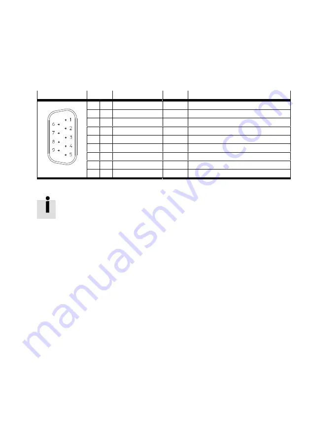
The CAN interface is already integrated in the motor controller CMMP‐AS‐...‐M3/-M0 and thus is always
available. The CAN bus connection is designed as a 9-pole DSUB plug in accordance with standards.
[X4]
Pin no.
Designation
Value
Description
1
–
–
Unused
6
CAN-GND
–
Ground
2
CAN-L
–
Negative CAN signal (dominant low)
7
CAN-H
–
Positive CAN signal (dominant high)
3
CAN-GND
–
Ground
8
–
–
Unused
4
–
–
Unused
9
–
–
Unused
5
CAN shield
–
Screening
Tab. 2.1
Pin assignment for CAN-interface [X4]
CAN bus cabling
When cabling the motor controller via the CAN bus, you should unconditionally observe
the following information and instructions to obtain a stable, trouble-free system.
If cabling is improperly done, malfunctions can occur on the CAN bus during operation.
These can cause the motor controller to shut off with an error for safety reasons.
Termination
A terminating resistor (120 Ω) can, if required, be switched by means of DIP switch S2 = 1 (CAN Term)
on the basic unit.
2.2.2
Cabling instructions
The CAN bus offers a simple, fail-safe ability to network all the components of a system together. But a
requirement for this is that all of the following instructions on cabling are observed.


