


Chapter 10 Troubleshooting
PAGE 10-26
10-12 RTC (Real Time Clock)
The AFC3000 Unit is equipped with an RTC (real time clock) for holding date and time data.
・
Model
ANG-RTC
・
Backup power source
Electric double layer capacitor
・
Backup duration in power OFF state Approx.
1000 hours
・
Power ON time needed for full charging of clock unit
1 hour
Be careful when using spare controllers, etc., because the time setting inside a Unit will be cleared if the
control power of the Unit is not turned on for 2 months or more.
Please perform time adjustment periodically because the clock loses time at a
rate of approximately 10 minutes a month.
●
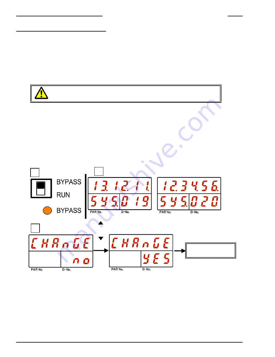
Procedures for Changing the Date/Time of a Unit (Indicator)
1. Switch the RUN/BYPASS switch of the Unit to the BYPASS side.
2. Operate the arrow pushbuttons to make “SYS” to be indicated at the PAR No., indication part and
“019” or “20” (“RTC: Year/Month/Day (Time)”) be indicated at the D-No. indication part and then press
the “
⊚
(SET)” pushbutton.
3. After transition to the set value editing mode, operate the arrow pushbuttons to change to the desired
date or time (“
▲”, “▼”: for incrementing/decrementing the value; “◄
“, “
►
”: for moving the cursor).
4. Press the “
⊚
(SET)” pushbutton, and within 2 seconds, press the “
▲
” or “
▼
” pushbutton to change
“NO” to “YES,” and then press the “
⊚
(SET)” pushbutton again.
5. Switch the RUN/BYPASS switch of the Unit to the RUN side.
* Besides the method of setting from the display, synchronization with the date/time of the PC can be
performed from the “Date/Time Setting” window of the AFC3000 User Console
[ ]
or
[ ]
4
1
Change of
Date/Time Setting
◎
(SET)
2
Summary of Contents for AFC3000
Page 1: ...AFC3000E HW 1 ...
Page 17: ......
Page 18: ...Chapter 1 Outline PAGE 1 1 Chapter 1 Outline 1 ...
Page 25: ......
Page 26: ...Chapter 2 Specifications PAGE 2 1 Chapter 2 Specifications 2 ...
Page 34: ...Chapter 3 System Description PAGE 3 1 Chapter 3 System Description 3 ...
Page 64: ...Chapter 4 Installation and Wiring PAGE 4 1 Chapter 4 Installation and Wiring 4 ...
Page 131: ...Chapter 4 Installation and Wiring PAGE 4 68 Blank Page ...
Page 132: ...Chapter 5 I O Expansion Unit Page 5 1 Chapter 5 I O Expansion Unit 5 ...
Page 164: ...Chapter 6 Power up and Initial Checks PAGE 6 1 Chapter 6 Power Up and Initial Checks 6 ...
Page 168: ...Chapter 7 Fastening Instructions PAGE 7 1 Chapter 7 Fastening Instructions 7 ...
Page 207: ... Blank Page ...
Page 208: ...Chapter 8 System Operation PAGE 8 1 Chapter 8 System Operation 8 ...
Page 259: ...Chapter 8 System Operation PAGE 8 52 ...
Page 260: ...Chapter 9 Maintenance Inspection PAGE 9 1 Chapter 9 Maintenance Inspection 9 ...
Page 268: ...Chapter 10 Troubleshooting PAGE 10 1 Chapter 10 Troubleshooting 10 ...
Page 294: ......


