


Chapter 8 System Operation
PAGE 8- 22
8-5 System Mode Change-Over – Multi / Single System
In order to change the system type, the controller must be turned to BYPASS Mode and Par No.000,
D-No.003 “Function Version” needs to be changed in the Parameter Edit Mode. Then the control power
must be rebooted.
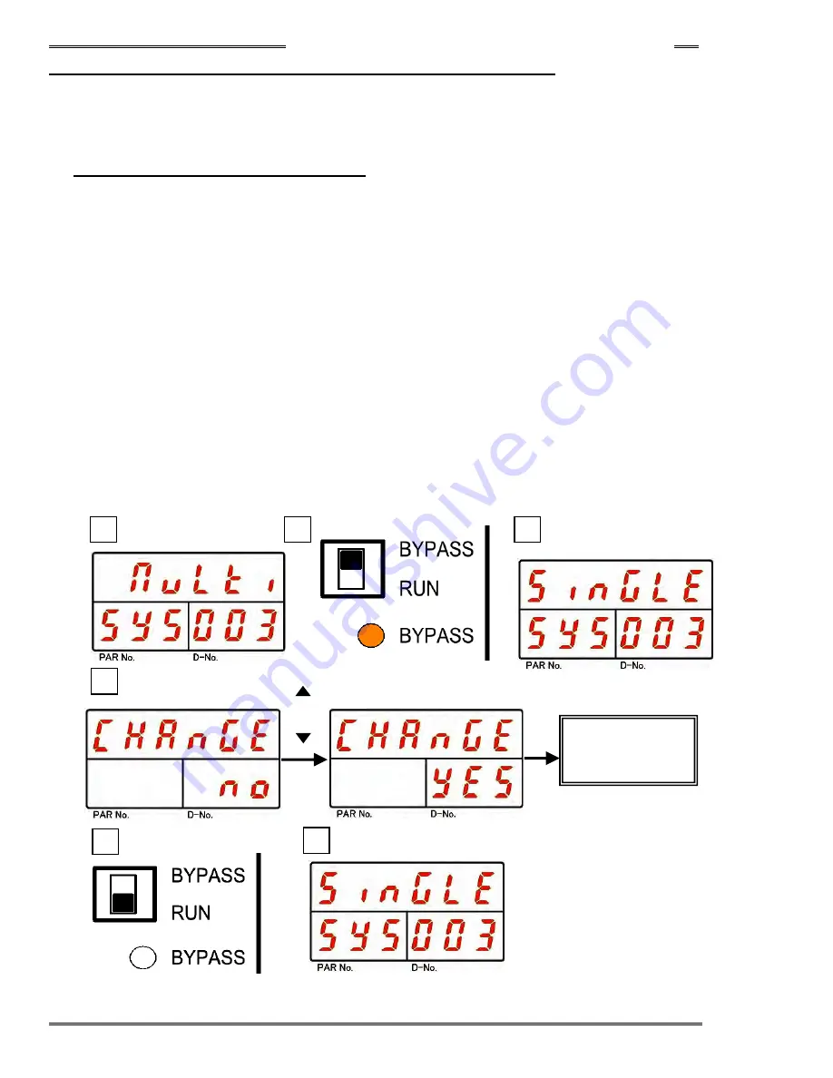
8-5-1 Multi System
→
Single System
1. Operate the arrow pushbuttons to make “System Display,” with “SYS” indicated in the PAR No. display
and “003” indicated in the D-No. display. (In case of a multi system, “Multi” is indicated on upper area of
the display (DATA))
2. Change the RUN/BYPASS switch of the Controller to the BYPASS position and then press the [SET]
pushbutton.
3. After transition to the Parameter Edit Mode, use the [
▲
] or [
▼
] pushbuttons to change to “Single.”
4. After pressing the [SET] pushbutton, use the [
▲
] or [
▼
] pushbuttons to change the indication from
“NO” to “YES” within 2 seconds, and then press the [SET] pushbutton again.
5. Change the RUN/BYPASS switch of the Controller to the RUN position.
6. Turn OFF the control power to the Controller.
7. By turning on the control power 10 seconds later, changing to the single system is accomplished.
8. To confirm the change to the single system, confirm that “Single” is indicated at the upper part of the
display in “System Display,” with “SYS” indicated in the PAR No. display and “003” indicated in the
D-No. display, in the System Parameter Display Mode.
[ ]
or
[ ]
8
5
3
4
1
Change of
System
Parameter
◎
(SET)
2
Summary of Contents for AFC3000
Page 1: ...AFC3000E HW 1 ...
Page 17: ......
Page 18: ...Chapter 1 Outline PAGE 1 1 Chapter 1 Outline 1 ...
Page 25: ......
Page 26: ...Chapter 2 Specifications PAGE 2 1 Chapter 2 Specifications 2 ...
Page 34: ...Chapter 3 System Description PAGE 3 1 Chapter 3 System Description 3 ...
Page 64: ...Chapter 4 Installation and Wiring PAGE 4 1 Chapter 4 Installation and Wiring 4 ...
Page 131: ...Chapter 4 Installation and Wiring PAGE 4 68 Blank Page ...
Page 132: ...Chapter 5 I O Expansion Unit Page 5 1 Chapter 5 I O Expansion Unit 5 ...
Page 164: ...Chapter 6 Power up and Initial Checks PAGE 6 1 Chapter 6 Power Up and Initial Checks 6 ...
Page 168: ...Chapter 7 Fastening Instructions PAGE 7 1 Chapter 7 Fastening Instructions 7 ...
Page 207: ... Blank Page ...
Page 208: ...Chapter 8 System Operation PAGE 8 1 Chapter 8 System Operation 8 ...
Page 259: ...Chapter 8 System Operation PAGE 8 52 ...
Page 260: ...Chapter 9 Maintenance Inspection PAGE 9 1 Chapter 9 Maintenance Inspection 9 ...
Page 268: ...Chapter 10 Troubleshooting PAGE 10 1 Chapter 10 Troubleshooting 10 ...
Page 294: ......


