Chapter 8 System Operation
PAGE 8- 19
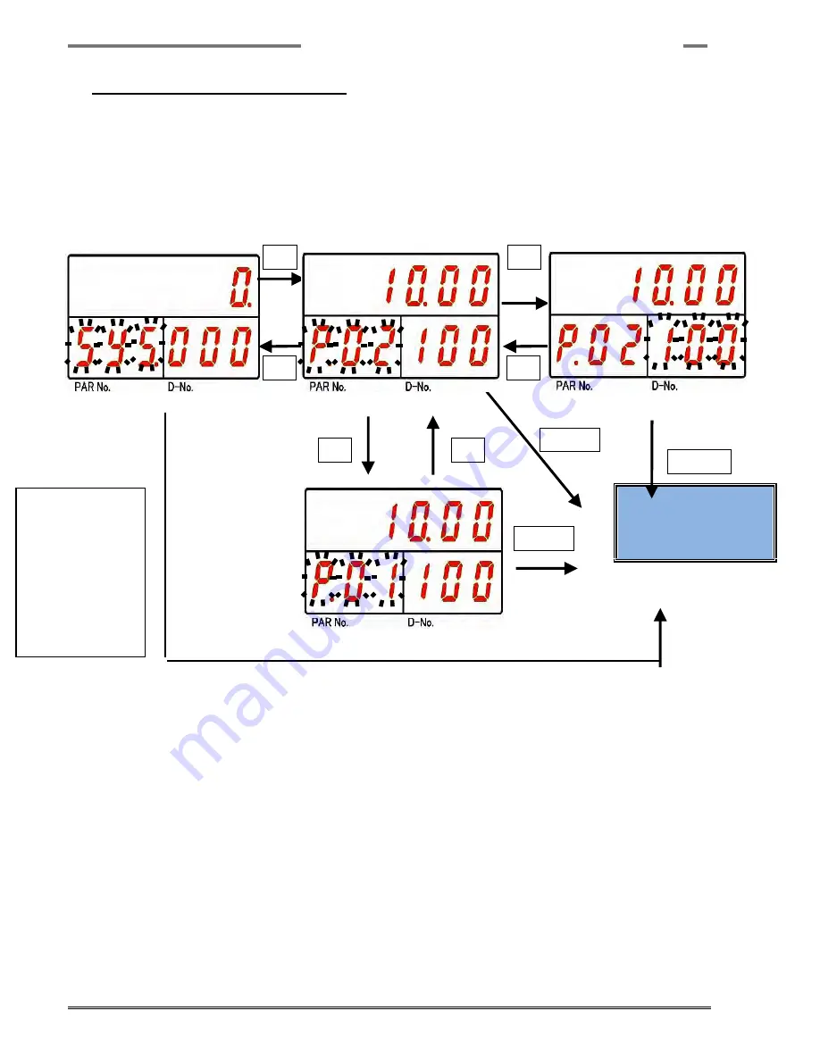
8-4-2 Parameter Selection Mode
Immediately after “Parameter Selection Mode” is established, the cursor (blinking number) is displayed on the
PAR No. Display when the [
◄
] push-button is pressed. When the [
►
] push-button is pressed, the cursor
(blinking number) is displayed on the D-No. Display.
The display set value of the cursor (blinking character) can be changed by ±1 using the [
▲
] or [
▼
]
push-button. The numbers can be advanced 10 at a time by holding the [
▲
] or [
▼
] push-button longer.
“Parameter Edit Mode” can be entered by pressing the [
◎
SET] push-button.
Parameter Edit Mode
(PAGE 8-18)
►
◄
▲
▼
◎
SET
◎
SET
◎
SET
►
◄
(By pressing the [
►
]
or [
◄
] pushbuttons,
you
can
quickly
change modes – in
this
example
System Parameter
to
Parameter
Select)
Summary of Contents for AFC3000
Page 1: ...AFC3000E HW 1 ...
Page 17: ......
Page 18: ...Chapter 1 Outline PAGE 1 1 Chapter 1 Outline 1 ...
Page 25: ......
Page 26: ...Chapter 2 Specifications PAGE 2 1 Chapter 2 Specifications 2 ...
Page 34: ...Chapter 3 System Description PAGE 3 1 Chapter 3 System Description 3 ...
Page 64: ...Chapter 4 Installation and Wiring PAGE 4 1 Chapter 4 Installation and Wiring 4 ...
Page 131: ...Chapter 4 Installation and Wiring PAGE 4 68 Blank Page ...
Page 132: ...Chapter 5 I O Expansion Unit Page 5 1 Chapter 5 I O Expansion Unit 5 ...
Page 164: ...Chapter 6 Power up and Initial Checks PAGE 6 1 Chapter 6 Power Up and Initial Checks 6 ...
Page 168: ...Chapter 7 Fastening Instructions PAGE 7 1 Chapter 7 Fastening Instructions 7 ...
Page 207: ... Blank Page ...
Page 208: ...Chapter 8 System Operation PAGE 8 1 Chapter 8 System Operation 8 ...
Page 259: ...Chapter 8 System Operation PAGE 8 52 ...
Page 260: ...Chapter 9 Maintenance Inspection PAGE 9 1 Chapter 9 Maintenance Inspection 9 ...
Page 268: ...Chapter 10 Troubleshooting PAGE 10 1 Chapter 10 Troubleshooting 10 ...
Page 294: ......


