


Chapter 10 Troubleshooting
PAGE 10-21
10-11 ETHERNET
Communication
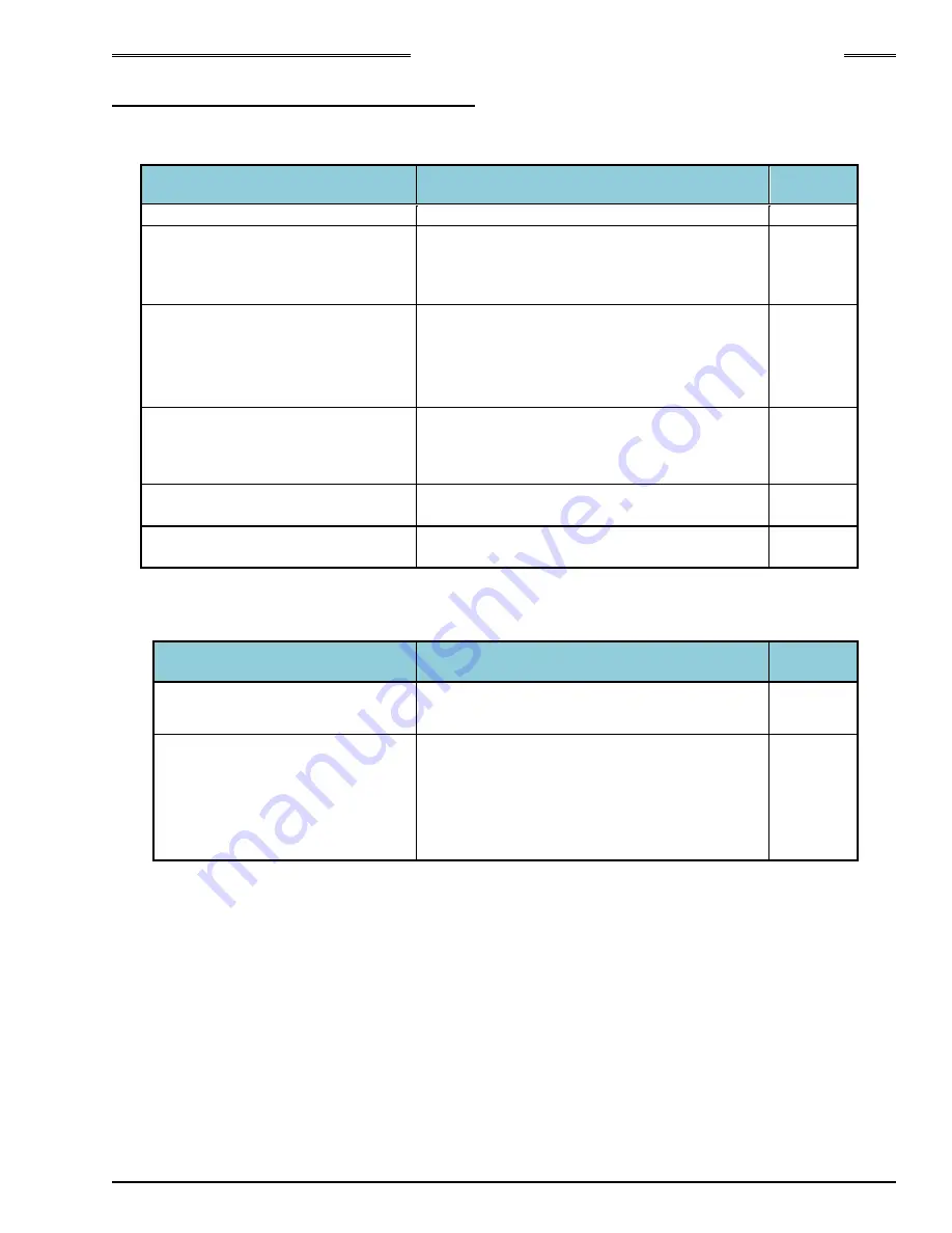
If your User Console PC cannot communicate with the MFC Unit through ETHERNET, refer to the chart
below and follow these trouble shooting steps.
Item
Countermeasure, Check Items
Referring
Section
Are the TCP/IP settings wrong?
Check the TCP/IP setting procedures
4-9
Is the cable connected to the
connector for communication
between spindles IN/OUT (AXIS
IN
・
AXIS OUT)?
Connect to the PC Communication Connector
(ETHERNET)
4-11
Is there any problem with the LAN
cable?
・
Use a crossover cable if PC and unit are
connected without a hub
・
Use a straight cable if PC and unit are
connected with a hub
・
Select a category 5e for LAN cable
4-9
Is the PC you’re using for
ETHERNET communication
capable of using a network
connection?
・
Set the PC to be able to use network or use
another PC which has network capability
Setting of Windows firewall
・
Disable the firewall temporarily because the
security level is high with the fire wall
10-11
Verify connection using the
command prompt
・
Enable to check the ETHERNET setting on
PC by using the command prompt.
10-11
Even if the communication does not have a problem, yet the data is not output correctly. Refer to the chart
below and follow the troubleshooting steps.
Item
Countermeasure, Check Items
Referring
Section
Data is not output at all
・
Verify that the protocol setting is correct
10-11
Part of the data is not output
・
Do not start a fastening operation by using a
sequence No. that is not set.
・
If an incorrect Unit Spindle No. is set, the
fastening results will not be output.
Check the sequence setting again and set the
correct Unit Spindle No.
Summary of Contents for AFC3000
Page 1: ...AFC3000E HW 1 ...
Page 17: ......
Page 18: ...Chapter 1 Outline PAGE 1 1 Chapter 1 Outline 1 ...
Page 25: ......
Page 26: ...Chapter 2 Specifications PAGE 2 1 Chapter 2 Specifications 2 ...
Page 34: ...Chapter 3 System Description PAGE 3 1 Chapter 3 System Description 3 ...
Page 64: ...Chapter 4 Installation and Wiring PAGE 4 1 Chapter 4 Installation and Wiring 4 ...
Page 131: ...Chapter 4 Installation and Wiring PAGE 4 68 Blank Page ...
Page 132: ...Chapter 5 I O Expansion Unit Page 5 1 Chapter 5 I O Expansion Unit 5 ...
Page 164: ...Chapter 6 Power up and Initial Checks PAGE 6 1 Chapter 6 Power Up and Initial Checks 6 ...
Page 168: ...Chapter 7 Fastening Instructions PAGE 7 1 Chapter 7 Fastening Instructions 7 ...
Page 207: ... Blank Page ...
Page 208: ...Chapter 8 System Operation PAGE 8 1 Chapter 8 System Operation 8 ...
Page 259: ...Chapter 8 System Operation PAGE 8 52 ...
Page 260: ...Chapter 9 Maintenance Inspection PAGE 9 1 Chapter 9 Maintenance Inspection 9 ...
Page 268: ...Chapter 10 Troubleshooting PAGE 10 1 Chapter 10 Troubleshooting 10 ...
Page 294: ......


