


Chapter 4 Installation and Wiring
PAGE 4-57
4-9 ETHERNET Interface
The ETHERNET interface is a dedicated TCP/IP Ethernet port to communicate with the AFC3000
User Console software installed on a PC (Windows®).
The following TCP/IP settings are set as (default) in the Unit. The settings at the PC side must thus be
changed when first connecting to the controller. (to communicate on the same network) Please refer to
the “TCP/IP Setup Procedures” on the following page regarding the TCP/IP setting method.
IP
address
192.168.11.10 (factory setting)
Subnet
Mask
255.255.255.0 (factory setting)
Default
Gateway
192.168.11.1 (factory setting)
Communication
Protocol
IEEE 802.3 compliant
ETHERNET Standard
100BASE-T
Communication Speed
100Mbps
Cable
Category 5 or higher (category 5 is
recommended)
Connector
Shape
RJ-45
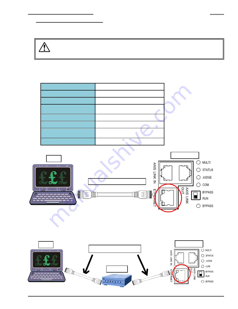
●
1-to-1 Direct Communication with the PC
*
Newer PC’s have auto-detect Ethernet hardware for signal direction and may not require a “Crossover”
cable. A common Ethernet (Straight) cable would work if this is the case.
●
Communication via an Ethernet Switch (Hub)
・
・
・
・
Do not connect the Ethernet communication cable to the AXIS LINK IN/OUT
connectors or damage may occur.
・
・
・
・
Connect the Ethernet Cable (for AFC Software Communication) to the MASTER Axis
Caution
Ethernet Crossover Cable*
Ethernet Straight Cable
PC
PC
Controller
Controller
Hub
Summary of Contents for AFC3000
Page 1: ...AFC3000E HW 1 ...
Page 17: ......
Page 18: ...Chapter 1 Outline PAGE 1 1 Chapter 1 Outline 1 ...
Page 25: ......
Page 26: ...Chapter 2 Specifications PAGE 2 1 Chapter 2 Specifications 2 ...
Page 34: ...Chapter 3 System Description PAGE 3 1 Chapter 3 System Description 3 ...
Page 64: ...Chapter 4 Installation and Wiring PAGE 4 1 Chapter 4 Installation and Wiring 4 ...
Page 131: ...Chapter 4 Installation and Wiring PAGE 4 68 Blank Page ...
Page 132: ...Chapter 5 I O Expansion Unit Page 5 1 Chapter 5 I O Expansion Unit 5 ...
Page 164: ...Chapter 6 Power up and Initial Checks PAGE 6 1 Chapter 6 Power Up and Initial Checks 6 ...
Page 168: ...Chapter 7 Fastening Instructions PAGE 7 1 Chapter 7 Fastening Instructions 7 ...
Page 207: ... Blank Page ...
Page 208: ...Chapter 8 System Operation PAGE 8 1 Chapter 8 System Operation 8 ...
Page 259: ...Chapter 8 System Operation PAGE 8 52 ...
Page 260: ...Chapter 9 Maintenance Inspection PAGE 9 1 Chapter 9 Maintenance Inspection 9 ...
Page 268: ...Chapter 10 Troubleshooting PAGE 10 1 Chapter 10 Troubleshooting 10 ...
Page 294: ......


