


Chapter 5
I/O
Expansion Unit
Page 5-13
●
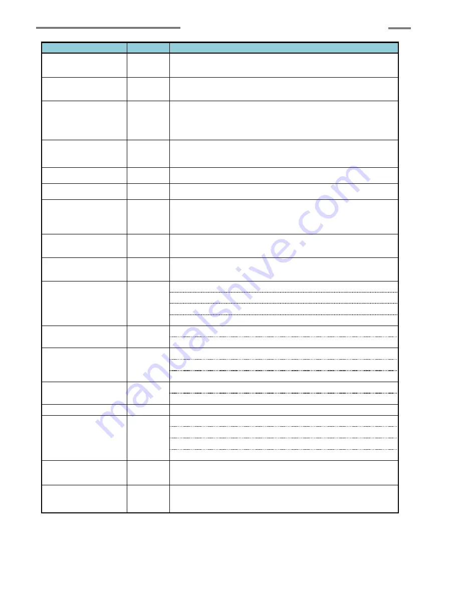
Individual Spindle Output Signals (spindle 1 to 32)
Signal
Connection
Description of Function/Usage
Reject
NO
Output when the fastening result is a REJECT. Indicates that the spindle
has failed achieving the fastening limits. This output remains active until
the START signal or RESET signal is input.
Accept
NO
Output when the fastening result is an ACCEPT. Indicates that the spindle
is within fastening limits. This output remains active until the START
signal or RESET signal is input.
Abnormal
NO
Output when an Abnormal condition occurs. This signal indicates that the
spindle has detected an internal fault and can no longer proceed. The
fault maybe generated during a self-check function (see AFC1500
Operation Manual for troubleshooting). The RESET signal clears the
abnormal condition.
Ready
NO
Output when the spindle is in the READY condition. Indicates spindle is
ready to operate and inputs are enabled. This signal is inactive (off) when
the BUSY output is active (on).
Busy
NO
Output after a START signal is received, and remains active until the
fastening cycle is complete and the READY signal is output.
Bypass
NO
Signal is active when the spindle is bypassed either from San Unit bypass
input signal or from the San Unit bypass switch.
Torque Hold
NO
Output while operating in D-
No. 315 “Torque Recovery Time” when the
fastening parameter D-No.
006 “After Fastening Operation” Torque
Recovery is enabled.
Parameter Select 1-4
NO
Output confirmation of PARAMETER SELECT 1~4 input selections.
Parameter Select bits are active according to what sequence is set from
the sequence select inputs.
Parameter Select 1-4
(Individual)
NO
Output confirmation of INDIV PARAMETER SELECT 1-32 input
selections. Parameter Select bits are active according to what
parameter is set from the parameter select inputs.
Torque Rejects
NO
Peak torque low limit /peak torque high limit
Final torque low limit/final torque high limit
Snug torque high limit
Start torque inhibit high limit
Angle Reject
NO
Final angle low limit/final angle high limit
Differential - angle /Differ angle
Rate Reject
NO
Rate 1 low limit/Rate 1 high limit
Rate 2 low limit /Rate 2 high limit
Rate 3 low limit /Rate 3 high limit
Time Reject
NO
1st time low limit /1st time high limit
2nd time low limit /2nd time high limit
Rundown Revolutions
NO
Rundown revolution low limit /rundown revolution high limit
Current/Voltage
Warnings
NO
Low current value limit warning/high current value limit warning
Current value error warning
CAL voltage error warning
ZERO voltage error warning
Combination Judgment
Bits 1-8
NO
Used to create “special” outputs formed by using a combination of MFC
Unit outputs in “AND / OR” logic.
Step Missed
NO
Output if one or more fastening steps was not processed during a
fastening operation. Used to confirm if the fastening sequence
processed correctly without skipping a programmed sequence step.
* NO: Normal Open
Summary of Contents for AFC3000
Page 1: ...AFC3000E HW 1 ...
Page 17: ......
Page 18: ...Chapter 1 Outline PAGE 1 1 Chapter 1 Outline 1 ...
Page 25: ......
Page 26: ...Chapter 2 Specifications PAGE 2 1 Chapter 2 Specifications 2 ...
Page 34: ...Chapter 3 System Description PAGE 3 1 Chapter 3 System Description 3 ...
Page 64: ...Chapter 4 Installation and Wiring PAGE 4 1 Chapter 4 Installation and Wiring 4 ...
Page 131: ...Chapter 4 Installation and Wiring PAGE 4 68 Blank Page ...
Page 132: ...Chapter 5 I O Expansion Unit Page 5 1 Chapter 5 I O Expansion Unit 5 ...
Page 164: ...Chapter 6 Power up and Initial Checks PAGE 6 1 Chapter 6 Power Up and Initial Checks 6 ...
Page 168: ...Chapter 7 Fastening Instructions PAGE 7 1 Chapter 7 Fastening Instructions 7 ...
Page 207: ... Blank Page ...
Page 208: ...Chapter 8 System Operation PAGE 8 1 Chapter 8 System Operation 8 ...
Page 259: ...Chapter 8 System Operation PAGE 8 52 ...
Page 260: ...Chapter 9 Maintenance Inspection PAGE 9 1 Chapter 9 Maintenance Inspection 9 ...
Page 268: ...Chapter 10 Troubleshooting PAGE 10 1 Chapter 10 Troubleshooting 10 ...
Page 294: ......


