


Chapter 8 System Operation
PAGE 8- 23
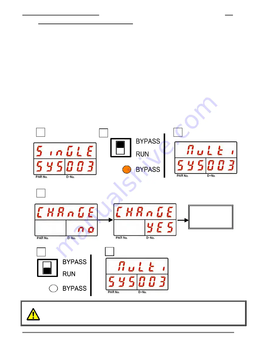
8-5-2 Single System
→
Multi System
1. Operate the arrow switches to make “System Indication,” with “SYS” indicated in the PAR No. display
and “003” indicated in the D-No. display. (In case of single system, “Single” is indicated on upper area of
the display (DATA))
2. Change the RUN/BYPASS switch of the Controller to the BYPASS position and then press the [SET]
pushbutton.
3. After transition to the set value editing mode, use the [
▲
] or [
▼
] pushbuttons to change to “Multi.”
4. After pressing the [SET] bushbutton, use the [
▲
] or [
▼
] pusbuttons to change the indication from “NO”
to “YES” within 2 seconds, and then press the [SET] pushbutton again.
5. Switch the RUN/BYPASS switch of the Controller to the RUN position.
6. Turn OFF the control power to the Controller.
7. By turning on the control power 10 seconds later, changing to the Multi System is accomplished.
8. To confirm the change to the Multi System, confirm that “Multi” is indicated at the upper part of the
display in “System Display,” with “SYS” indicated in the PAR No. display and “003” indicated in the D-No.
display, in the System Parameter Display Mode.
・・・・
Depending on the Master/Slave setting, a MASTER may have to be set when changing to
MULTI mode. The display must be removed and the setting of the SW1 switch on the
Controller front panel must be changed to change the system. Please refer to “Special
Function Switch SW1 Settings” in Section 4-12-2
8
5
3
4
1
Change of
System
Parameter
◎
(SET)
2
[▲]
or
[▼]
Summary of Contents for AFC3000
Page 1: ...AFC3000E HW 1 ...
Page 17: ......
Page 18: ...Chapter 1 Outline PAGE 1 1 Chapter 1 Outline 1 ...
Page 25: ......
Page 26: ...Chapter 2 Specifications PAGE 2 1 Chapter 2 Specifications 2 ...
Page 34: ...Chapter 3 System Description PAGE 3 1 Chapter 3 System Description 3 ...
Page 64: ...Chapter 4 Installation and Wiring PAGE 4 1 Chapter 4 Installation and Wiring 4 ...
Page 131: ...Chapter 4 Installation and Wiring PAGE 4 68 Blank Page ...
Page 132: ...Chapter 5 I O Expansion Unit Page 5 1 Chapter 5 I O Expansion Unit 5 ...
Page 164: ...Chapter 6 Power up and Initial Checks PAGE 6 1 Chapter 6 Power Up and Initial Checks 6 ...
Page 168: ...Chapter 7 Fastening Instructions PAGE 7 1 Chapter 7 Fastening Instructions 7 ...
Page 207: ... Blank Page ...
Page 208: ...Chapter 8 System Operation PAGE 8 1 Chapter 8 System Operation 8 ...
Page 259: ...Chapter 8 System Operation PAGE 8 52 ...
Page 260: ...Chapter 9 Maintenance Inspection PAGE 9 1 Chapter 9 Maintenance Inspection 9 ...
Page 268: ...Chapter 10 Troubleshooting PAGE 10 1 Chapter 10 Troubleshooting 10 ...
Page 294: ......


