Menus 15 to 17
SM-Uni Enc Pl
Parameter
structure
Keypad and
display
Parameter
x.00
Parameter
description format
Advanced parameter
descriptions
Macros
Serial comms
protocol
Electronic
nameplate
Performance RFC mode
264
Unidrive SP Advanced User Guide
www.controltechniques.com Issue Number: 10
Trips can be enabled/disabled using Pr
x.17
as follows:
The binary sum defines the level of error detection as below:
If the SSI power supply bit monitor feature is enabled, ensure that this has been configured for an encoder setup Pr
x.09
, Pr
x.11
.
In order for the phase error detection to function correctly the LPR of the SC.HiPEr, SC.EndAt and SC.SSI encoder must be greater than 9 x number
of motor poles (e.g 54 for a 6 pole servo motor).
Trip suppression mode
If bit 3 is set and #3.26 does not select this option module as the feedback device, trips 1 to 6 (encoder trips during normal running) will not trip the
drive. They will still be serviced locally, for example the power supply will be turned off if an overload condition occurs.
When this mode is active and a trip occurs, the option module will set x.49 (freeze encoder position) to alert the user that a trip has been suppressed.
The trip number will still be written to x.50, but a drive trip request will not be made (Slx.Er). The action of resetting the drive resets the flag (x.49) and
the trip (x.50).
SC.HiPEr, SC.EndAt, EndAt
When an SC.HiPEr, SC.EndAt or EndAt encoder is being used, the Solutions Module will interrogate the encoder on power-up. If Pr x.18 is set to one
and the encoder type is recognized based on the information provided by the encoder, the Solutions Module will set-up.
1. The encoder turns / linear encoder comms to sine wave ratio (Pr
x.09
)
2. The equivalent lines per revolution (Pr
x.10
)
3. The encoder comms resolution / linear encoder comms bits (Pr
x.11
)
For SC.HiPEr or SC.EndAt encoders the rotary encoder select (Pr
x.16
) is also set up. If the encoder is not recognized, there is a comms error or the
resulting parameter values are out of range the Solutions Module initiates a trip 7 or 12 to 16 trip to prompt the user to enter the information. The
Solutions Module can auto-configure with any of the following devices.
Rotary EndAt encoders
The encoder turns, comms resolution and equivalent lines per rev are set up directly using the data read from the encoder.
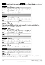
x.17
Error detection level
RW
Uni
US
Ú
0 to 15
Ö
0
Update rate: Background read
Bit
Function
0
Wire break detect
1
Phase error detect
2
SSI power supply monitor
3
Suppress trips 1 to 6 if not used as feedback
Bit 3
Bit 2
Bit 1
Bit 0
Error detection level
Pr x.17
0
0
0
0
Error detection disabled
0
0
0
0
1
Wire break detect
1
0
0
1
0
Phase error detect
2
0
0
1
1
Wire break + phase error detect
3
0
1
0
0
SSI power supply bit monitor
4
0
1
0
1
Wire break + SSI power supply bit monitor
5
0
1
1
0
Phase error SSI power supply bit monitor
6
0
1
1
1
Wire break phase error SSI power supply bit monitor
7
1
0
0
0
Error detection di trips suppressed
8
1
0
0
1
Wire break detect suppressed
9
1
0
1
0
Phase error detect suppressed
10
1
0
1
1
Wire break supp phase error detect suppressed
11
1
1
0
0
SSI power supply bit suppressed
12
1
1
0
1
Wire break supp SSI power supply bit suppressed
13
1
1
1
0
Phase error detect supp SSI power supply bit suppressed
14
1
1
1
1
Wire break detect supp phase error detect supp SSI power supply bit suppressed
15
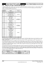
x.18
Auto configuration enable / SSI binary format select
RW
Bit
US
Ú
OFF (0) or On (1)
Ö
OFF (0)
Update rate: Background read
NOTE
NOTE
Summary of Contents for unidrive sp
Page 419: ......
Page 420: ...0471 0002 10 ...

