


Parameter
structure
Keypad and
display
Parameter
x.00
Parameter
description format
Advanced parameter
descriptions
Macros
Serial comms
protocol
Electronic
nameplate
Performance RFC mode
Menu 6
Unidrive SP Advanced User Guide
147
Issue Number: 10 www.controltechniques.com
Full scale voltage measurement and the over voltage trip level are defined by DC_VOLTAGE_MAX. However, the maximum level of the low voltage
battery supply voltage should not normally exceed 90% of this value to avoid spurious over voltage trips.
The drive thermal model system normally controls the fan speed, however the fan can be forced to operate at full speed if this parameter is set to 1.
When this is set to 1 the fan remains at full speed until 10s after this parameter is set to zero.
Note when the drive is in the UU state, the fan always runs at minimum speed.
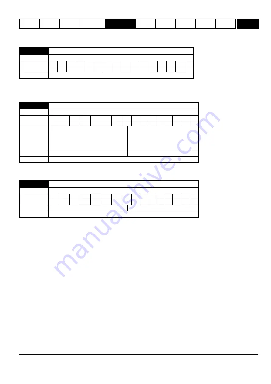
This parameter defines the nominal supply voltage when operating in low voltage mode. The parameter is used to define the braking IGBT switching
threshold and the over voltage trip level for low voltage battery mode (see Pr
6.44
).
SP0xxx, SP1xxx, SP2xxx and SP3xxx
Drives in these sizes ranges have a diode rectifier input stage with no direct monitoring system. Mains loss and phase loss detection is derived from
the DC bus voltage. This parameter has no effect.
SP4xxx, SP5xxx and SP6xxx
Drives in these sizes ranges have an active rectifier input stage that is used to control DC bus charging. Mains loss and phase loss detection is
derived from the DC bus voltage. The only status information taken from the input rectifier stage is an over temperature indication which gives an
Oht4 trip if active. This parameter has no effect on this feature. When the control system is leaving the mains loss ride through condition (ACUU) it is
important that no load is applied to the input rectifier until it is fully active. This feature can be disabled by setting this parameter to one.
SPMxxxx
Drives in this size range can use an active rectifier input stage that is used to control DC bus charging. These drives can be operated as a single
power module or the power modules can be operated in parallel. Mains and phase loss detection is derived from the DC bus voltage, but additional
monitoring is provided by the input rectifier controller as follows:
1. An over temperature indication from a single module or any module operating in parallel causes an Oht4.P trip if it is present for more than 0.5s.
This feature is not affected by this parameter.
2. A phase loss indication from a single module or any module operating in parallel causes a PH.P trip if it is present for more than 0.5s. If this
parameter is set to one, the drive is operating in regen mode or the drive is operating from a low voltage supply this feature is disabled.
3. A mains loss indication from any, but not all modules operating in parallel causes a PH.P trip if this condition is present for more than 0.5s. If this
parameter is set to one, the drive is operating in regen mode or the drive is operating from a low voltage supply this feature is disabled.
When the control system is leaving the mains loss ride through condition (ACUU) it is important that no load is applied to the input rectifier until it is
fully active. This feature can be disabled by setting this parameter to one.
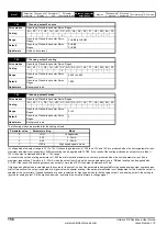
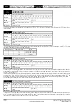
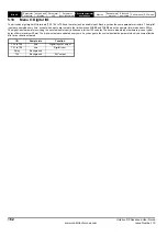
6.45
Force cooling fan to run at full speed
Drive modes
Open-loop, Closed-loop vector, Servo, Regen
Coding
Bit
SP
FI
DE
TE VM DP ND RA NC NV
PT
US RW BU
PS
1
1
1
Update rate
Background read
6.46
Nominal low voltage battery supply
Drive modes
Open-loop, Closed-loop vector, Servo, Regen
Coding
Bit
SP
FI
DE
TE
VM
DP
ND RA NC NV PT US RW BU PS
1
1
1
1
Range
48 to 72 for SP0xxx drives
48 to 48 for SP1xxx drives
48 to 72 for SP2xxx and SP3xxx drives
48 to 72 for all other 200V drives
48 to 96 for all other 400V and 690V drives
Default
Open-loop, Closed-loop vector, Servo, Regen
48
Update rate
Background read
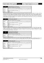
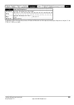
6.47
Disable mains/phase loss detection from input rectifier
Drive modes
Open-loop, Closed-loop vector, Servo
Coding
Bit
SP
FI
DE
TE
VM
DP
ND RA NC NV PT US RW BU PS
1
1
1
Default
Open-loop, Closed-loop vector, Servo
0
Update rate
Background read
Summary of Contents for unidrive sp
Page 419: ......
Page 420: ...0471 0002 10 ...


