


Parameter
structure
Keypad and
display
Parameter
x.00
Parameter
description format
Advanced parameter
descriptions
Macros
Serial comms
protocol
Electronic
nameplate
Performance RFC mode
Menus 15 to 17
SM-Uni Enc Pl
Unidrive SP Advanced User Guide
263
Issue Number: 10 www.controltechniques.com
.
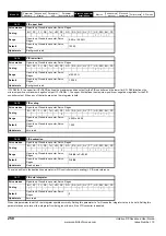
Encoder termination select
Ab, Fd, Fr, Ab.SErvo, Fd.SErvo, Fr.SErvo.
The terminations may be enabled/disabled by this parameter as follows:
SC- Not used
Pr
x.16
has no effect
SC.SErvo
U-U\, V-V\, W-W\ and Sin and Cos signals are terminated and cannot be disabled.
SC.HiPEr, SC.EndAt, SC.SSI - Rotary encoder select
If Pr
x.16
is set to 1 or 2 the encoder is a rotary encoder and the following applies
1. Pr
x.09
defines the number of turns bits in the comms message from the encoder and a mask is applied to Pr
x.04
to remove turns bits in excess
of those provided in the encoder comms position.
2. Pr
x.11
defines the number of comms bits used to define a single turn.
If Pr
x.16
is set to 0 the encoder is a linear encoder and the following apply:
1. Pr
x.09
defines the ratio between the length of a sine wave period and the length of the least significant comms bit.
2. No mask is applied to the turns displayed in Pr
x.04
.
3. Pr
x.11
defines the number of comms bits used to give the whole position value.
If the position feedback device is SC.HiPEr or SC.EndAt it is possible for the drive to set up this parameter automatically from information obtained
from the encoder (see Pr
x.18
).
EndAt, SSI - Comms only encoder mode
If this parameter is set to 1 or 2 the drive always takes the complete absolute position for these comms only type encoders. The turns (Pr
x.04
),
position (Pr
x.05
) and fine position (Pr
x.06
) will be an exact representation of the position from the encoder.
If the encoder does not provide 16bits of turns information, the internal representation of the turns used by the position controller in Menu 13 and
functions within the SM-Applications Module such as the Advanced Position Controller, rolls over at the maximum position value from the encoder.
This jump in position is likely to cause unwanted effects.
EndAt
The EndAt format includes a CRC that is used by the drive to detect corrupted data, and so if the position data has been corrupted the drive uses the
previous correct data until new uncorrupted data is received.
If this parameter is set to 0 the drive only takes the absolute position directly from the encoder during initialisation. The change of position over each
sample is then used to determine the current position. This method always gives 16 bits of turns information that can be used without jumps in
position by the position controller in Menu13 and SM-applications modules etc. This method will only operate correctly if the change of position over
any 250
μ
s period is less than 0.5 of a turn, or else the turns information will be incorrect. The turns can then only be corrected by re-initializing the
encoder.This problem should not occur with EndAt encoders because three consecutive corrupted messages at the slowest sample rate (i.e. 250
μ
s)
would be required even at the maximum speed of 40,000rpm before the change of position would be the required 0.5 turns to give possible corruption
of the turns information. If three consecutive messages with CRC errors occur this will cause the drive to produce an EnC5 trip. The drive can only be
re-enabled after the trip is reset which will re-initialize the encoder and correct the absolute turns
SSI
As the SSI format does not include any error checking and it is not possible for the drive to detect if the position data has been corrupted. The benefit
of using the absolute position directly from an SSI encoder is that even if the encoder communications are disturbed by noise and position errors
occur, the position will always recover the correct position after the disturbance has ceased.
Under normal operating conditions and at a maximum speed of 40,000rpm the maximum change of position is less than 0.5 turns, however, if noise
corrupts the data from an SSI encoder it is possible to have apparent large change of position, and this can result in the turns information becoming
and remaining corrupted until the encoder is re-initialized.
If an SSI encoder is used, but is not powered from the drive, and the encoder is powered up after the drive, it is possible that the first change of
position detected could be large enough to cause the problem described above. This can be avoided if the encoder interface is initialized via Pr
3.47
after the encoder has powered up. If the encoder includes a bit that indicates the status of the power supply the power supply monitor should be
enabled (see Pr
x.17
). This will ensure that the drive remains tripped until the encoder is powered up and the action of resetting the trip will reinitialise
the encoder interface.
x.16
Encoder termination/rotary encoder select/comms
only encoder mode
RW
Txt
US
Ú
0 to 2
Ö
1
Update rate: Background read
Encoder input
Pr x.16=0
Pr x.16=1
Pr x.16=2
A-A\
Disabled
Enabled
Enabled
B-B\
Disabled
Enabled
Enabled
Z-Z\
Disabled
Disabled
Enabled
U-U\, V-V\, W-W\
Enabled
Enabled
Enabled
Summary of Contents for unidrive sp
Page 419: ......
Page 420: ...0471 0002 10 ...