Parameter
structure
Keypad and
display
Parameter
x.00
Parameter
description format
Advanced parameter
descriptions
Macros
Serial comms
protocol
Electronic
nameplate
Performance RFC mode
Menu 8
Unidrive SP Advanced User Guide
165
Issue Number: 10 www.controltechniques.com
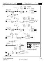
T29 digital input 6
??.??
Any
unprotected
bit
parameter
??.??
8.26
T29 digital
input 6
destination
x(-1)
8.16
T29 digital
input 6
invert
T29 digital
input 6 state
8.06
8.29
29
6.31
Jog forward
I.O polarity
select
8.27
Relay
source
8.17
Relay source
invert
??.??
Any bit
parameter
??.??
x(-1)
Relay
state
8.07
10.01
Drive
Healthy
41
42
0V
0.XX
0.XX
Key
Read-write (RW)
parameter
Read-only (RO)
parameter
Input
terminals
Output
terminals
X
X
X
X
This logic diagram applies only when all
parameters are at their default settings
8.25
T28 digital
input 5
destination
??.??
Any
unprotected
bit
parameter
??.??
x(-1)
8.15
T28 digital
input 5
invert
T28 digital
input 5 state
8.05
8.29
28
1.41
Analogue input 1 /
input 2 select
I.O polarity
select
T28 digital input 5
8.10
Drive enable
mode
select
Drive enable
10.32
External trip
Drive enable
Drive enable
indicator
8.09
x(-1)
31
T22 24V output
Any
unprotected
bit
parameter
??.??
8.28
T22 24V output source
x(-1)
8.18
T22 24V output
source
invert
T22 24V
output
state
8.08
0.00
??.??
22
T27 digital input 4
??.??
Any
unprotected
bit
parameter
??.??
8.24
T27 digital input 4
destination
x(-1)
8.14
T27 digital
input 4
invert
T27 digital
input 4 state
8.04
8.29
I.O polarity
select
27
6.32
Run reverse
Stop/start
logic select
6.04
1.14
8.39
T28 & T29 digital
input auto-selection
disable*
Reference
selector*
Summary of Contents for unidrive sp
Page 419: ......
Page 420: ...0471 0002 10 ...


