Chapter 5: System Setup
39
Configuring Hardware Setup
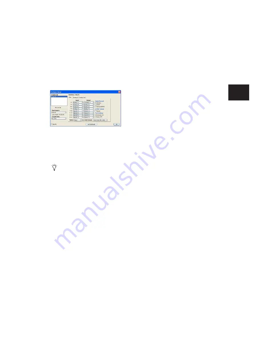
The Main page of the Hardware Setup dialog is
where you define which physical inputs and
outputs on your audio interface are routed to
available inputs and outputs in Pro Tools.
Additional pages are available to configure other
controls for each audio interface (such as setting
operating levels). For details, refer to the
Getting
Started
Guide
for your system, or to the guide for
your audio interface.
To configure audio interfaces on a Pro Tools|HD
system:
1
Choose Setup > Hardware.
2
From the Peripherals list, select the Digidesign
audio interface connected to the first card in
your system. This will be the interface at the top
of the list.
3
Click the Main tab.
4
From the Clock Source pop-up menu, select
the appropriate clock source for the system. In
many cases, you will use Internal. The other
choices are for resolving Pro Tools to external
clock sources. Depending on your audio inter-
face, Clock Source options can include:
AES/EBU [Encl], S/PDIF, Optical [Encl], AES/EBU
1–8, TDIF, ADAT, and Word Clock (optional
Word Clock rates are available when operating
at higher sample rates).
5
From the Ext. Clock Output pop-up menu, se-
lect the appropriate clock output to send to de-
vices attached to your audio interface.
6
Select which digital I/O port on your audio in-
terface enclosure is active under Digital Format.
Choices include: AES/EBU, S/PDIF, and Optical
(S/PDIF). Selecting Optical (S/PDIF) resets the
Optical I/O port (which is, by default, eight
channels of ADAT I/O) to two channels of
S/PDIF Optical I/O.
7
For S/PDIF compatibility with Tascam DA-30
DAT recorders select the Tascam option under
S/PDIF Format.
8
For the 96 I/O and 96i I/O, click the Meters
pop-up menu and select whether to meter the
input or output signal.
9
From the Input and Output pop-up menus, se-
lect the physical ports (such as Analog 1–2 or
Optical 1–2), that will be routed to the corre-
sponding Pro Tools input and output channels
(such as Ch 1–2 or Ch 3–4), listed on the left side
of the Main page.
Inputs and outputs of similar format are differ-
entiated in the input and output channel pop-
up menus. For example, the AES/EBU inputs
and outputs in the 192 I/O enclosure are listed
as AES/EBU [Encl], while the AES/EBU inputs
and outputs on the factory-installed Digital I/O
card are listed (in pairs) as AES/EBU 1–2,
AES/EBU 3–4, AES/EBU 5–6, and AES/EBU 7–8.
Hardware Setup dialog for 96 I/O (Main page)
Identify audio interface connections at any
time by selecting the interface name in the
Peripherals list, then clicking Identify. All
the LEDs on the interface front panel illu-
minate.
Summary of Contents for Pro Tools
Page 1: ...Pro Tools Reference Guide Version 7 3 ...
Page 15: ...1 Part I Introduction ...
Page 16: ...2 ...
Page 33: ...19 Part II System Configuration ...
Page 34: ...20 ...
Page 44: ...Pro Tools Reference Guide 30 ...
Page 94: ...Pro Tools Reference Guide 80 ...
Page 95: ...81 Part III Sessions Tracks ...
Page 96: ...82 ...
Page 108: ...Pro Tools Reference Guide 94 ...
Page 130: ...Pro Tools Reference Guide 116 ...
Page 269: ...255 Part IV Recording ...
Page 270: ...256 ...
Page 310: ...Pro Tools Reference Guide 296 ...
Page 345: ...331 Part V Editing ...
Page 346: ...332 ...
Page 402: ...Pro Tools Reference Guide 388 ...
Page 496: ...Pro Tools Reference Guide 482 ...
Page 548: ...Pro Tools Reference Guide 534 ...
Page 571: ...557 Part VI MIDI Editing ...
Page 572: ...558 ...
Page 596: ...Pro Tools Reference Guide 582 ...
Page 637: ...623 Part VII Mixing ...
Page 638: ...624 ...
Page 702: ...Pro Tools Reference Guide 688 ...
Page 771: ...757 Part VIII Video Sync Surround ...
Page 772: ...758 ...
Page 792: ...Pro Tools Reference Guide 778 ...
Page 806: ...Pro Tools Reference Guide 792 ...
Page 856: ...Pro Tools Reference Guide 842 ...


