Chapter 3 Connections and Wiring
|
ASDA-A&A+ Series
3-24
Revision April 2009
DI
Signal
DI
Code
Assigned
Control
Mode
Pin No.
(Default)
Details
(*2)
Wiring Diagram
(Refer to 3.3.4)
MD0
33
Pr
-
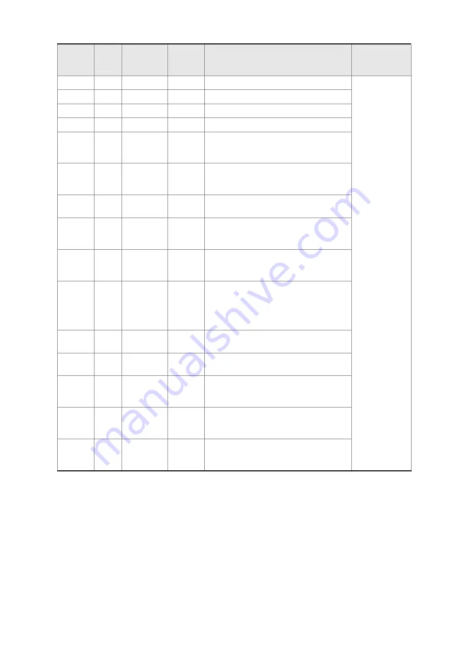
Feed step mode input 0 (bit 0)
MD1
34
Pr
-
Feed step mode input 1 (bit 1)
MDP0
35
Pr
-
Manually continuous operation
MDP1
36
Pr
-
Manually single step operation
JOGU 37 ALL
-
Forward JOG input. When JOGU is
activated, the motor will JOG in forward
direction. [see P4-05]
JOGD 38 ALL
-
Reverse JOG input. When JOGD is
activated, the motor will JOG in reverse
direction. [see P4-05]
STEPU 39
Pr
-
Step up input. When STEPU is activated,
the motor will run to next position.
STEPD 40
Pr
-
Step down input. When STEPD is
activated, the motor will run to previous
position.
STEPB 41
Pr
-
Step back input. When STEPB is
activated, the motor will return to first
position.
AUTOR 42
Pr
-
Auto run input. When AUTOR is activated,
the motor will run automatically according
to internal position command. For time
interval setting, please see P2-52 to P2-
59.
GNUM0 43
Pt, Pr, Pt-S,
Pr-S
-
Electronic gear ratio (Numerator) selection
0 [See P2-60~P2-62]
GNUM1 44
Pt, Pr, Pt-S,
Pr-S
-
Electronic gear ratio (Numerator) selection
1 [See P2-60~P2-62]
INHP 45 Pt,
Pt-S -
Pulse inhibit input. When the drive is in
position mode, if INHP is activated, the
external pulse input command is not valid.
STF 46
S, Sz, Pt-S,
Pr-S, S-T
-
Enable motor forward operation. In speed
mode, it is used to enable the motor
forward operation.
STB 47
S, Sz, Pt-S,
Pr-S, S-T
-
Enable motor reverse operation. In speed
mode, it is used to enable the motor
reverse operation.
C9/C10
Footnote *2:
The "state" of the input function may be turned ON or OFF as it will be dependant on the
settings of P2-10~P2-17.
Call 1(800)985-6929 for Sales
deltaacdrives.com
Call 1(800)985-6929 for Sales
deltaacdrives.com


