


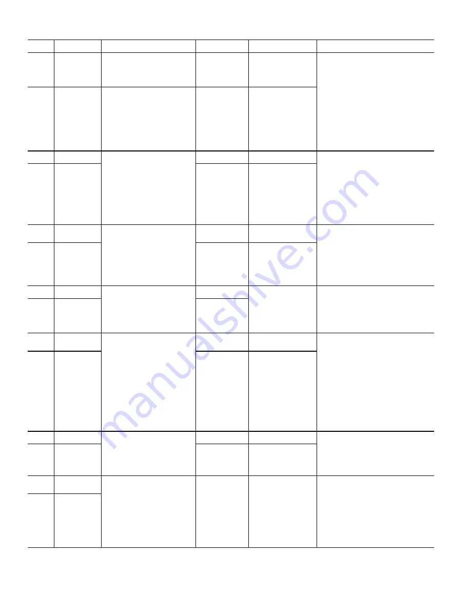
214
10037
Circ A - High Con-
densing tempera-
ture out of map
compressor
The alarm will trip if discharge pres-
sure (DP_A) > 304.2 psi (2097 kPa). If
discharge pressure exceeds compres-
sor envelope for more than 60 sec-
onds, trip alarm. If SCT > 161°F
(71.7°C), trip alarm.
Circuit A will be shut
down immediately.
Manual
If this condition is encountered, check the fol-
lowing items for faults:
•
noncondensables in the refrigerant circuit
•
condenser air recirculation
•
proper refrigerant charge (undercharged)
•
EXV operation
•
operation beyond the limits of the machine
•
condenser coils for debris or restriction
•
condenser fans and motors for proper ro-
tation and operation
•
the discharge service valves to be sure
that they are open
•
check the discharge pressure transducer
for accuracy
•
confirm unit configuration
10038
Circ B - High Con-
densing tempera-
ture out of map
compressor
The alarm will trip if discharge pres-
sure (DP_B) > 304.2 psi (2097 kPa). If
discharge pressure exceeds compres-
sor envelope for more than 60 sec-
onds, trip alarm. If SCT > 161°F
(71.7°C), trip alarm.
Circuit B will be shut
down immediately.
Manual
10067
Circuit A Low Oil
Pressure
Tested only when the compressor is
ON
The alarm will trip if the compressor
has been running for more than 60s
and oil pressure is lower than the
required level for more than 15s OR
The alarm will trip if the oil transducer
out of range for 5s (see oil transducer
alarms 12010 and 12011)
Circuit A will be shut
down.
Manual
If this condition is encountered, check the fol-
lowing items for faults:
•
sensor wiring to SIOB
•
board for faulty channel
•
faulty transducer
•
plugged oil filter
•
faulty oil solenoid valve coil
•
stuck oil solenoid valve
•
confirm manual service valves are fully
open
•
confirm unit configuration
10068
Circuit B Low Oil
Pressure
Circuit B will be shut
down.
Manual
10070
Circuit A Max Oil
Filter Differential
Pressure
Tested when compressor is running:
The alarm will trip if the differential oil
pressure is greater than 50 psig for
more than 30s
Circuit A will be shut
down.
Manual
If this condition is encountered, check the fol-
lowing items for faults:
•
discharge and oil sensor wiring to SIOB
•
boards for a faulty channel
•
faulty transducer
•
plugged oil filter
•
faulty oil solenoid valve
•
stuck oil solenoid valve
•
confirm manual service valve is fully open
10071
Circuit B Max Oil
Filter Differential
Pressure
Circuit B will be shut
down.
Manual
10075
Circuit A Low Oil
Level
When the compressor is running or
off. The alarm will trip if the compres-
sor is running and the oil level switch
is opened for more than 10 seconds
NOTE:
When the units starts the oil level
switch is verified after 2 minutes.
Circuit A will be shut
down.
Automatic, first or second
occurrence in 24 hours OR
Manual, if the alarm has
occurred more than 3 times
in the previous 24 hours
If this condition is encountered, check the fol-
lowing items for faults:
•
oil level in the oil separator
•
oil level switch wiring to the SIOB
•
board for a faulty channel
•
faulty oil level switch
•
oil solenoid valve stuck open
10076
Circuit B Low Oil
Level
Circuit B will be shut
down.
10078
Circuit A High Dis-
charge Gas Tem-
perature
Tested when compressor is running:
The alarm will trip if the discharge gas
temperature is higher than 210°F
(98.89°C) for more than 90s OR
higher than 215°F (101.6°C) for any
period of time
Circuit A will be shut
down
Manual
If this condition is encountered, check the fol-
lowing items for faults:
•
noncondensables in the refrigerant circuit
•
condenser air recirculation
•
proper refrigerant charge (undercharged)
•
EXV operation
•
operation beyond the limits of the machine
•
condenser coils for debris or restriction
•
condenser fans and motors for proper ro-
tation and operation
•
the discharge service valves to be sure
that they are open
•
check the discharge pressure transducer
for accuracy
•
confirm unit configuration
10079
Circuit B High Dis-
charge Gas Tem-
perature
Circuit B will be shut
down
Manual
10081
Circuit A Suction
Valve closed
Tested when compressor is running.
The alarm will trip if economizer pres-
sure < suction pressure -14 psi (96.52
kPa) during startup
Circuit A will be shut
down
Manual
If this condition is encountered, check the fol-
lowing items for faults:
•
confirm suction service valve is fully open
(if equipped)
•
compressor strainer for debris
•
sensor wiring (economizer pressure trans-
ducer and suction pressure transducer)
10082
Circuit B Suction
Valve closed
Circuit B will be shut
down
Manual
10084
Circuit A High Oil
Filter Drop Pres-
sure
Tested when compressor is running.
The alarm will trip if the difference
between the Circuit Discharge Pres-
sure and the Compressor Oil Pressure
is greater than 30 psi (206.8 kPa) for
more than 5 minutes
No action on the unit Manual
If this condition is encountered, check the fol-
lowing items for faults:
•
sensor wiring to SIOB (discharge pressure
transducer and oil pressure transducer)
•
board for faulty channel
•
faulty transducer
•
plugged oil filter
•
faulty oil solenoid valve coil
•
stuck oil solenoid valve
•
confirm manual service valves are fully
open
10085
Circuit B High Oil
Filter Drop Pres-
sure
Table 168 — Alarm Details by Code (cont)
ALARM
CODE
ALARM NAME
CRITERIA
FOR TRIP
ACTION TAKEN
BY CONTROL
RESET
METHOD
POSSIBLE CAUSES/CORRECTIVE ACTIONS
Summary of Contents for AquaForce 30XV140
Page 79: ...79 Fig 76 VFD Communication Wiring Compressor A B Fan VFD A1 A2 B1 B2...
Page 228: ...228 Fig 90 30XV Typical Field Wiring Schematic cont...
Page 229: ...229 Fig 91 30XV Standard Tier 140 275 All Voltages Power Schematic NOTE See Legend on page 226...
Page 230: ...230 Fig 92 30XV Standard Tier 300 325 All Voltages Power Schematic NOTE See Legend on page 226...
Page 240: ...240 Fig 99 30XV Communication Wiring...
Page 241: ...241 Fig 100 30XV 115V Control Wiring All Tonnages All Voltages...
Page 242: ...242 Fig 101 30XV 24V Control Wiring 30XV140 325 All Voltages...
Page 243: ...243 Fig 101 30XV 24V Control Wiring 30XV140 325 All Voltages cont...
Page 244: ...244 Fig 102 30XV 24V Control Wiring 30XV350 500 All Voltages...
Page 245: ...245 Fig 102 30XV 24V Control Wiring 30XV350 500 All Voltages cont...
Page 246: ...246 Fig 103 Component Arrangement Diagram for 30XV140 325...
Page 247: ...247 Fig 103 Component Arrangement Diagram for 30XV140 325 cont...
Page 248: ...248 Fig 104 Component Arrangement Diagram for 30XV350 500...
Page 337: ...337 APPENDIX J FACTORY SUPPLIED PUMPS cont Fig L System Information...
Page 338: ...338 APPENDIX J FACTORY SUPPLIED PUMPS cont Fig M Unit and Language Settings...
Page 341: ...341 APPENDIX J FACTORY SUPPLIED PUMPS cont Fig P Data Input 2...
Page 342: ...342 APPENDIX J FACTORY SUPPLIED PUMPS cont Fig Q Data Input 3...
Page 347: ...347 APPENDIX J FACTORY SUPPLIED PUMPS cont Fig U Pump Wiring Diagram...


