4-11
4.7.2
Installing the Right Side of the Chassis
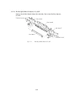
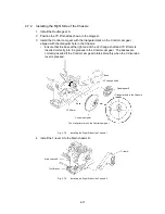
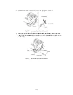
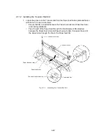
1. Install the Double gear S.
2. Position the YC lift shaft as shown in the diagram.
3. Install the Control cam gear with the triangular mark on the Control cam gear
aligned with the triangular hole in the Chassis.
∗
Ensure that the boss at the right end of the LF change shaft and YC lift arm is
inserted correctly into the grooves in the Control cam gear. The bosses are
correctly inserted if the Control cam gear rotates smoothly when the Y-diversion
lever is pressed.
Fig. 4.7-3
Installing the Right Side of the Chassis 1
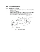
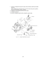
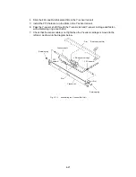
4. Install the T-lever A to the Main chassis R.
T-lever A
Main chassis R
T-cutter assy
Fig. 4.7-4
Installing the Right Side of the Chassis 2
Control cam gear
The triangular mark on the Control cam gear
Triangular hole in the Chassis
Double gear S
LF change shaft
Boss
Boss
YC lift arm
Summary of Contents for LX-1200
Page 1: ...SERVICE MANUAL MODEL LX 1200 LX 300 ...
Page 2: ...COOL LAMINATOR SERVICE MANUAL MODEL LX 1200 LX 300 ...
Page 5: ...Chapter 1 SPECIFICATIONS ...
Page 9: ...Chapter 2 MECHANISMS ...
Page 20: ...Chapter 3 DISASSEMBLY PROCEDURES ...
Page 58: ...Chapter 4 ASSEMBLY PROCEDURES ...
Page 105: ...Chapter 5 ELECTRONIC CONTROLLERS ...
Page 127: ...Chapter 6 MAINTENANCE ...
Page 149: ...Chapter 7 TROUBLESHOOTING ...

