i
CONTENTS
Chapter 3. DISASSEMBLY PROCEDURES
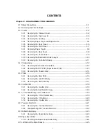
3.1 Safety
Precautions ............................................................................................................ 3-1
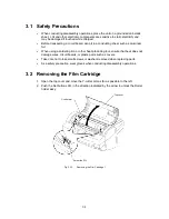
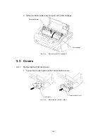
3.2 Removing the Film Cartridge ............................................................................................ 3-1
3.3 Covers ............................................................................................................................... 3-2
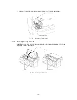
3.3.1 Removing the Trimmer Cover .............................................................................. 3-2
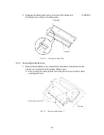
3.3.2 Removing the Top Cover B .................................................................................. 3-3
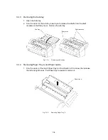
3.3.3 Removing the Sub-tray ......................................................................................... 3-4
3.3.4 Removing Paper Tray A and Paper Guide........................................................... 3-4
3.3.5 Removing the Body Cover.................................................................................... 3-5
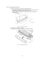
3.3.6 Removing the Front Cover.................................................................................... 3-7
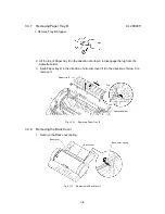
3.3.7 Removing Paper Tray B ....................................................................................... 3-8
3.3.8 Removing the Back Cover .................................................................................... 3-8
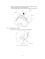
3.3.9 Removing the Cover Switch ................................................................................. 3-9
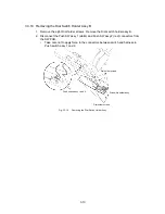
3.3.10 Removing the Dial Switch Holder Assy B .......................................................... 3-10
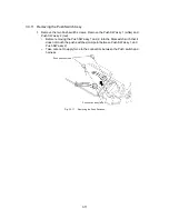
3.3.11 Removing the Push Switch Assy........................................................................ 3-11
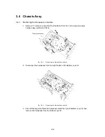
3.4 Chassis
Assy................................................................................................................... 3-12
3.4.1 Removing the Harness Connectors ................................................................... 3-12
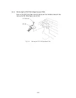
3.4.2 Removing the PST PCB (Paper Sensor PCB)................................................... 3-13
3.4.3 Removing the Chassis Assy............................................................................... 3-14
3.5 PCBs ............................................................................................................................... 3-16
3.5.1 Removing the Main PCB .................................................................................... 3-16
3.5.2 Removing the Jack PCB Assy............................................................................ 3-16
3.5.3 Removing the SW PCB Assy ............................................................................. 3-17
3.6 X-cutter
Unit .................................................................................................................... 3-18
3.6.1 Removing the X-cutter Unit................................................................................. 3-18
3.6.2 Removing the Leaf Switch F Assy...................................................................... 3-18
3.7 Y-CA Chassis Assy and Y-cutter Arm ............................................................................ 3-19
3.7.1 Removing the Y-CA Chassis Assy ..................................................................... 3-19
3.7.2 Removing the Y-CA Motor.................................................................................. 3-20
3.7.3 Removing the Y-cutter Arm ................................................................................ 3-20
3.8 Y-sensor Rail Unit ........................................................................................................... 3-21
3.8.1 Removing the Y-sensor Rail Unit ....................................................................... 3-21
3.8.2 Disassembling the Y-sensor Rail Unit ................................................................ 3-22
3.9 Roller Holder Assy .......................................................................................................... 3-23
3.9.1 Removing the Roller Holder Assy ...................................................................... 3-23
3.10 Paper Feed Roller ........................................................................................................... 3-24
3.10.1 Removing the Paper Feed Holder Assy ............................................................. 3-24
3.11 Left Side of the Main Chassis ......................................................................................... 3-25
Summary of Contents for LX-1200
Page 1: ...SERVICE MANUAL MODEL LX 1200 LX 300 ...
Page 2: ...COOL LAMINATOR SERVICE MANUAL MODEL LX 1200 LX 300 ...
Page 5: ...Chapter 1 SPECIFICATIONS ...
Page 9: ...Chapter 2 MECHANISMS ...
Page 20: ...Chapter 3 DISASSEMBLY PROCEDURES ...
Page 58: ...Chapter 4 ASSEMBLY PROCEDURES ...
Page 105: ...Chapter 5 ELECTRONIC CONTROLLERS ...
Page 127: ...Chapter 6 MAINTENANCE ...
Page 149: ...Chapter 7 TROUBLESHOOTING ...

