4-31
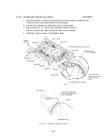
4.16.3 Installing the Harness Connectors CL2000011
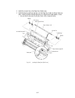
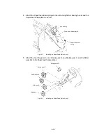
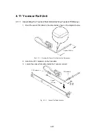
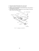
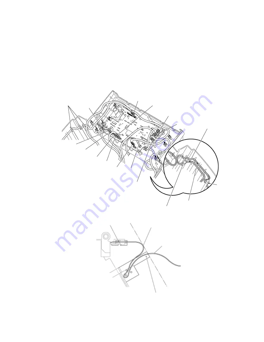
1. Attach the harness connectors (except the power harness assy) to the Main PCB
according to the color sequence shown in the diagram.
2. Connect the harnesses along the paths shown in the diagram.
3. Tape harnesses *1, *3, and *4 to the right face of Bottom cover B.
Pass the *5 Black (4P) cable through the three harness retainers.
4. Install the F cable as shown in the diagram below.
Yellow (2P)
White (4P)
*4 Yellow, blue, white, red, gray (5P)
Black (6P)
Installation of the
*1, *3, *4 harnesses.
F cable
*5 Black (4P)
Tape
Installation of the *2 harness.
Red (2P)
*3 Blue (2P)
*1 Orange (2P)
Black (2P)
*2 Red (5P)
Harness
retainers
White (2P)
Insert the core with
the harness wound on
it to the rib in the
cover.
FPC holder A
Pass the F cable loosely
round the tips of the lugs on
the Cassette holder.
Cassette holder lug
F cable
Fig. 4.16-5
Installing the Harness Connectors
(6P)
Summary of Contents for LX-1200
Page 1: ...SERVICE MANUAL MODEL LX 1200 LX 300 ...
Page 2: ...COOL LAMINATOR SERVICE MANUAL MODEL LX 1200 LX 300 ...
Page 5: ...Chapter 1 SPECIFICATIONS ...
Page 9: ...Chapter 2 MECHANISMS ...
Page 20: ...Chapter 3 DISASSEMBLY PROCEDURES ...
Page 58: ...Chapter 4 ASSEMBLY PROCEDURES ...
Page 105: ...Chapter 5 ELECTRONIC CONTROLLERS ...
Page 127: ...Chapter 6 MAINTENANCE ...
Page 149: ...Chapter 7 TROUBLESHOOTING ...

