4-33
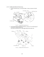
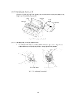
4.17.2 Installing the Dial Switch Holder Assy
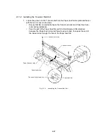
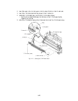
1. Connect the Push SW assy 1 and Push SW assy 2 harness connectors to the SW
PCB.
Push SW assy 1 (white)
Push SW assy 2 (red)
Push SW assy 2
Harness connector (red)
Dial Switch holder
Push SW assy 1
Harness connector (white)
Switch PCB
Fig. 4.17-2
Installing the Dial Switch Holder Assy 1
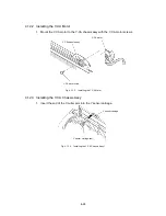
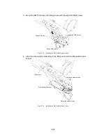
2. Turn over the Body cover and attach the Start key, Stop key, Two-connection switch,
Continuous key, and Extra border key.
Check that the LED lenses are correctly aligned with the front of the cover.
Start key
LED lens
LED lenses
Continuous key
Stop key
Extra border key
Two-connection switch
Fig. 4.17-3
Installing the Dial Switch Holder Assy 2
Summary of Contents for LX-1200
Page 1: ...SERVICE MANUAL MODEL LX 1200 LX 300 ...
Page 2: ...COOL LAMINATOR SERVICE MANUAL MODEL LX 1200 LX 300 ...
Page 5: ...Chapter 1 SPECIFICATIONS ...
Page 9: ...Chapter 2 MECHANISMS ...
Page 20: ...Chapter 3 DISASSEMBLY PROCEDURES ...
Page 58: ...Chapter 4 ASSEMBLY PROCEDURES ...
Page 105: ...Chapter 5 ELECTRONIC CONTROLLERS ...
Page 127: ...Chapter 6 MAINTENANCE ...
Page 149: ...Chapter 7 TROUBLESHOOTING ...


