4-25
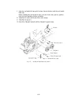
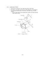
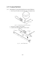
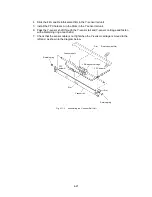
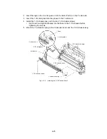
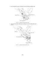
2. Insert the lugs on the Y-cutter guide L into the slots (Part A) on the Y-cutter arm.
3. Insert the Y-CA timing belt into the groove in the Y-cutter arm.
4. Install the Y-CA chassis assy with the two Y-CA chassis screws.
∗
Set the left and right Embosses into the holes in the Y-CA chassis before
tightening the screws.
5. Attach the Y extension spring to the Y-diversion lever and the Y-CA chassis assy.
Y-cutter guide L
Part A
Y-CA sensor carriage
Y-cutter arm
Y-CA timing belt
Y-cutter arm
Y-CA chassis assy
Y extension spring
Y-CA chassis screws
Fig. 4.12-5
Installing the Y-CA Chassis Assy 2
Summary of Contents for LX-1200
Page 1: ...SERVICE MANUAL MODEL LX 1200 LX 300 ...
Page 2: ...COOL LAMINATOR SERVICE MANUAL MODEL LX 1200 LX 300 ...
Page 5: ...Chapter 1 SPECIFICATIONS ...
Page 9: ...Chapter 2 MECHANISMS ...
Page 20: ...Chapter 3 DISASSEMBLY PROCEDURES ...
Page 58: ...Chapter 4 ASSEMBLY PROCEDURES ...
Page 105: ...Chapter 5 ELECTRONIC CONTROLLERS ...
Page 127: ...Chapter 6 MAINTENANCE ...
Page 149: ...Chapter 7 TROUBLESHOOTING ...

