2-3
S
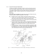
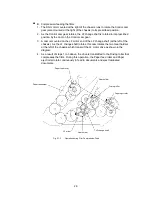
B. Compression-feeding the films
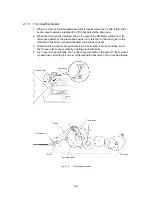
1. The SG motor mounted at the right of the chassis runs to rotate the Control cam
gear (also mounted at the right of the chassis) to its prescribed position.
2. As the Control cam gear rotates, the LF change shaft is rotated to its prescribed
position by the cam on the Control cam gear.
3. A cam is mounted on the LF motor end of the LF change shaft (at the left of the
chassis). As the LF change shaft rotates, this cam rotates the two Gear holders
at the left of the chassis, which transmit the LF motor drive as shown in the
diagram.
4. As a result of steps 1 to 3 above, the drive is transmitted to the Driving roller that
compresses the films. During this operation, the Paper feed roller and Paper
eject roller rotate continuously to feed in documents and eject laminated
documents.
Gear holder
Driving roller
Paper eject roller
LF change shaft
Gear holder
LF motor
Paper feed holder
Paper feed roller
Fig. 2.1-3
Operation during Film Compression-Feed
Summary of Contents for LX-1200
Page 1: ...SERVICE MANUAL MODEL LX 1200 LX 300 ...
Page 2: ...COOL LAMINATOR SERVICE MANUAL MODEL LX 1200 LX 300 ...
Page 5: ...Chapter 1 SPECIFICATIONS ...
Page 9: ...Chapter 2 MECHANISMS ...
Page 20: ...Chapter 3 DISASSEMBLY PROCEDURES ...
Page 58: ...Chapter 4 ASSEMBLY PROCEDURES ...
Page 105: ...Chapter 5 ELECTRONIC CONTROLLERS ...
Page 127: ...Chapter 6 MAINTENANCE ...
Page 149: ...Chapter 7 TROUBLESHOOTING ...

