


5-4
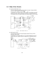
5.3 Main
PCB
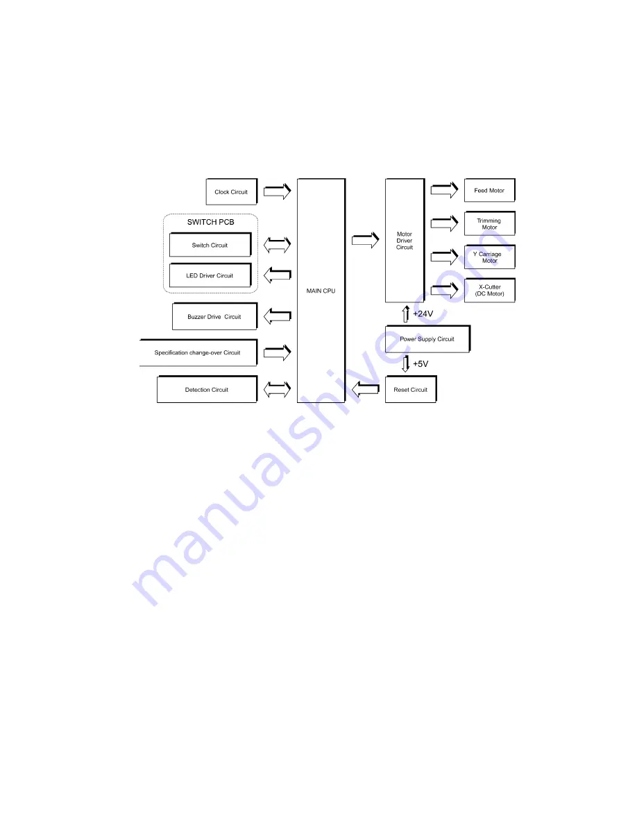
Fig. 5.3-1 shows a block diagram of the electrical parts.
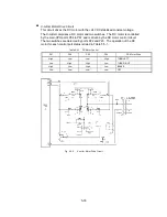
The Main PCB comprises the CPU, detector circuits (including switch status detection),
motor drive circuits, and power circuits.
Fig. 5.3-1
Block Diagram of the Electrical Parts
S
Main CPU
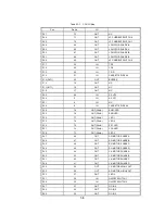
The main CPU is an 8-bit CMOS microcontroller that controls the overall system.
The main CPU incorporates 1 kB RAM, 32 kB ROM, and 72 I/O ports.
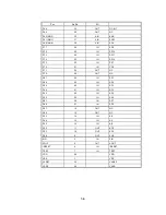
The I/O map for the I/O ports is shown in Table 5.3-1 overleaf.
Summary of Contents for LX-1200
Page 1: ...SERVICE MANUAL MODEL LX 1200 LX 300 ...
Page 2: ...COOL LAMINATOR SERVICE MANUAL MODEL LX 1200 LX 300 ...
Page 5: ...Chapter 1 SPECIFICATIONS ...
Page 9: ...Chapter 2 MECHANISMS ...
Page 20: ...Chapter 3 DISASSEMBLY PROCEDURES ...
Page 58: ...Chapter 4 ASSEMBLY PROCEDURES ...
Page 105: ...Chapter 5 ELECTRONIC CONTROLLERS ...
Page 127: ...Chapter 6 MAINTENANCE ...
Page 149: ...Chapter 7 TROUBLESHOOTING ...


