7-11
5
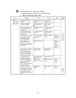
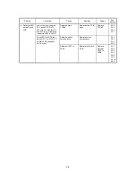
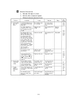
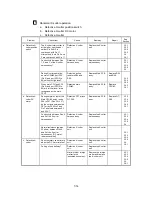
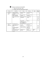
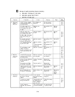
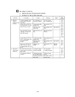
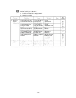
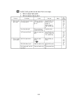
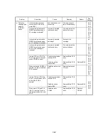
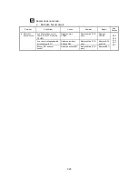
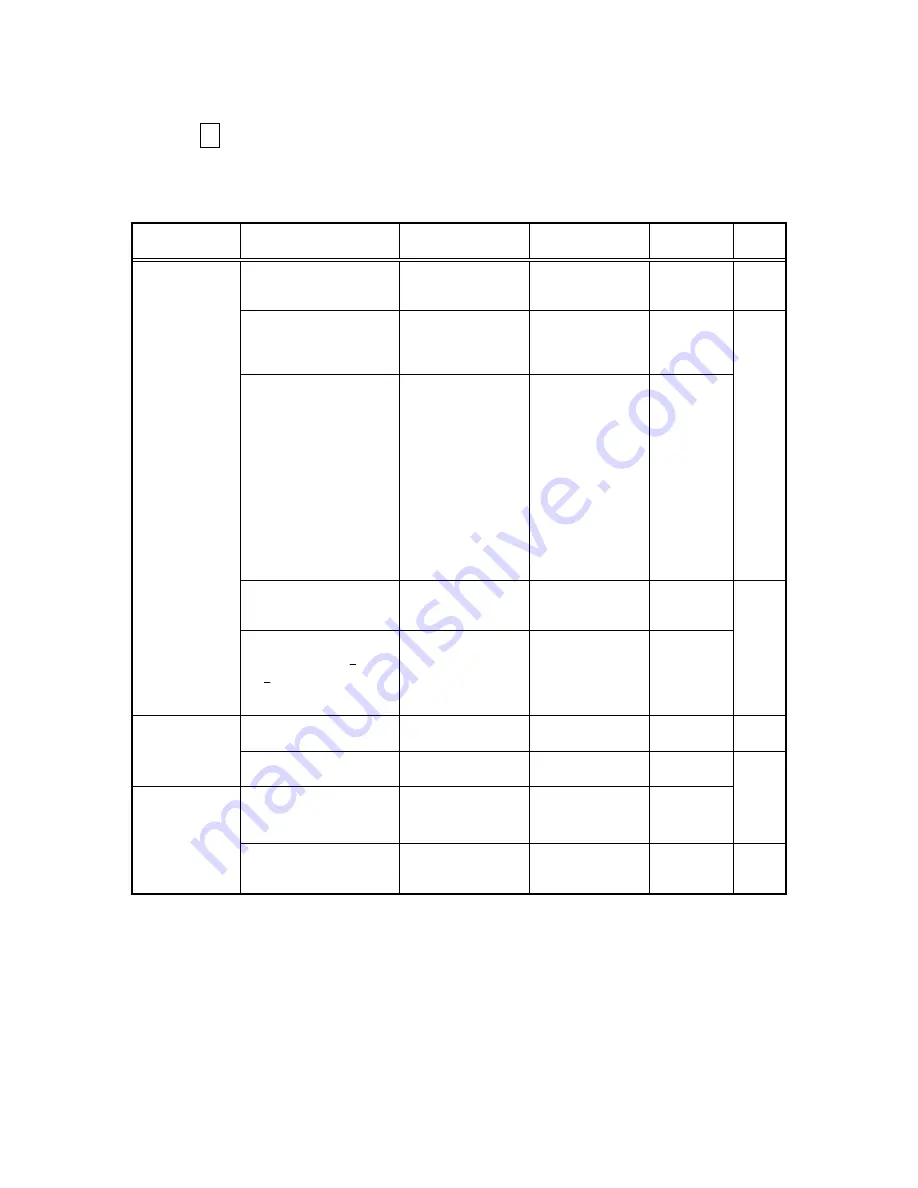
Abnormal manual feed
a. Defective film feed (LF) motor.
b. Defective film compression system.
c. Problem related to paper eject roller.
Problem Check
Item
Cause Remedy
Repair
See
Section
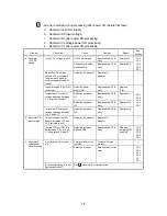
Is the black lead connector
connected to CN12 on the
Main PCB?
Motor harness assy
not connected.
Correctly connect
the motor harness
assy.
3.3.3
3.3.4
3.3.5
Are pulses output from
output ports P01 to P04 (Pin
66 to Pin 69) of the main
CPU#3?
Defective main
CPU#3.
Replace Main PCB
assy.
Replace
CPU#3.
During High output of the
Main CPU #3 output ports
P02 and P03 (Pins 67, 68)
when the outputs of P01
and P64 (Pins 66, 69) are
Low and the output of either
or both P05 and P00 (Pins
70 and 65) is Low, are the
driver #6 OUT 1 (Pin 9) and
OUT 4 (Pin 19) outputs
approximately 24 V and the
OUT 2 (Pin 11) and OUT 3
(Pin 15) outputs
approximately 0 V?
Defective driver #6.
Replace Main PCB
assy.
Replace #6.
3.3.3
3.3.4
3.3.5
3.4.2
3.5.1
Conductivity in motor
harness assy?
Defective motor
harness assy.
Replace motor
harness assy for LF
motor.
a. Defective film
feed (LF)
motor
Is the resistance value
correct (approx. 5.5 ohms)
between phases A-
A
and
B-
B
of the LF motor (PM
motor L)?
Defective LF motor.
Replace LF motor.
3.3.1
3.3.3
3.3.4
3.3.5
3.4
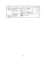
Are top and bottom feed
rollers correctly engaged?
Roller holder unit is
incorrectly set up.
Correctly set up the
roller holder unit.
6.2
b. Defective film
compression
system.
Is film correctly placed
between the feed rollers?
Defective cassette
setting.
Set the cassette
correctly.
Film or other foreign matter
stuck to top or bottom paper
eject roller.
Foreign matter stuck
to roller.
Clean off foreign
matter.
3.3.1
3.3.3
3.3.4
3.3.5
3.4
3.13
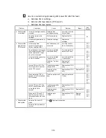
c. Problem
related to
paper eject
roller
Do the top and bottom
paper eject rollers move
smoothly?
Problem with paper
eject rollers.
Apply KS64F silicon
grease to the four
bearings.
Summary of Contents for LX-1200
Page 1: ...SERVICE MANUAL MODEL LX 1200 LX 300 ...
Page 2: ...COOL LAMINATOR SERVICE MANUAL MODEL LX 1200 LX 300 ...
Page 5: ...Chapter 1 SPECIFICATIONS ...
Page 9: ...Chapter 2 MECHANISMS ...
Page 20: ...Chapter 3 DISASSEMBLY PROCEDURES ...
Page 58: ...Chapter 4 ASSEMBLY PROCEDURES ...
Page 105: ...Chapter 5 ELECTRONIC CONTROLLERS ...
Page 127: ...Chapter 6 MAINTENANCE ...
Page 149: ...Chapter 7 TROUBLESHOOTING ...

