6-20
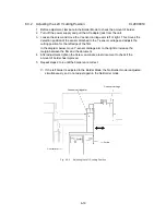
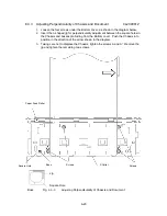
6.3.3 Adjusting Perpendicularity of Chassis and Document CL2000012
1. Loosen the four screws under the Bottom cover, as shown in the diagram below.
2. Insert the L-shaped jig for perpendicularity adjustment between the square holes in
the Chassis and bosses protruding from the Bottom cover. Push the Chassis into
position in the direction of the arrow shown in the diagram.
3. Taking care not to displace the Chassis, tighten the screws A and A'. Remove the
jig and tighten the remaining two screws.
Fig. 6.3-3
Adjusting Perpendicularity of Chassis and Document
Paper Feed Roller
Square Hole
Boss
Screws
X Cutter
Screws
Jig
Square Hole
Boss
Summary of Contents for LX-1200
Page 1: ...SERVICE MANUAL MODEL LX 1200 LX 300 ...
Page 2: ...COOL LAMINATOR SERVICE MANUAL MODEL LX 1200 LX 300 ...
Page 5: ...Chapter 1 SPECIFICATIONS ...
Page 9: ...Chapter 2 MECHANISMS ...
Page 20: ...Chapter 3 DISASSEMBLY PROCEDURES ...
Page 58: ...Chapter 4 ASSEMBLY PROCEDURES ...
Page 105: ...Chapter 5 ELECTRONIC CONTROLLERS ...
Page 127: ...Chapter 6 MAINTENANCE ...
Page 149: ...Chapter 7 TROUBLESHOOTING ...

