4-38
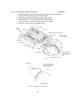
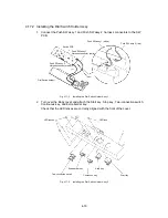
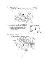
2. Put the Body cover on the Bottom cover, slightly in front of its correct position.
Insert the Paper tray B into the paper feed slot in the Body cover.
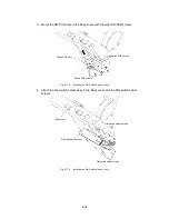
3. Insert the Y-cutter guide R lug into the slots in the Dial SW assy in front of the Body
cover.
Body cover
Paper tray B
Dial switch assy
Slot
Y-cutter guide R
Lug
Fig. 4.17-12 Installing the Body Cover 2
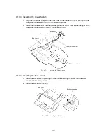
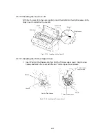
4. Push the Body cover down while holding down the Y-diversion lever.
∗
Take care not to apply too much force. Not much force is required if Step 3 is
conducted correctly.
5. Check that the two hooks at the front of the Body cover are engaged. Repeat from
step 2 if the hooks are not engaged.
6. Check that the two hooks at the sides of the Body cover are engaged. Press down
on Part A if the hooks are not engaged.
7. Push down the rear of the Body cover to engage the six hooks.
Body cover
Side hooks
Front hooks
Y-diversion lever
Rear hooks
Bottom cover B
Part A
Part A
Fig. 4.17-13 Installing the Body Cover 3
Summary of Contents for LX-1200
Page 1: ...SERVICE MANUAL MODEL LX 1200 LX 300 ...
Page 2: ...COOL LAMINATOR SERVICE MANUAL MODEL LX 1200 LX 300 ...
Page 5: ...Chapter 1 SPECIFICATIONS ...
Page 9: ...Chapter 2 MECHANISMS ...
Page 20: ...Chapter 3 DISASSEMBLY PROCEDURES ...
Page 58: ...Chapter 4 ASSEMBLY PROCEDURES ...
Page 105: ...Chapter 5 ELECTRONIC CONTROLLERS ...
Page 127: ...Chapter 6 MAINTENANCE ...
Page 149: ...Chapter 7 TROUBLESHOOTING ...

