3-27
3.12 Right Side of the Main Chassis
3.12.1 Removing the Right Side of the Chassis
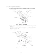
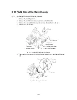
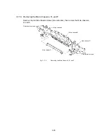
1. Remove the two Idle gears A.
2. Remove the two SG motor screws and remove the SG motor.
3. Remove the Leaf switch SG screw, then remove the Leaf switch SG assy.
4. Remove the T-lever shaft.
SG motor
SG motor screws
Idle gears A
Chassis R support screw
Leaf switch SG assy screw
T-lever shaft
Leaf switch SG assy
Chassis R support
Fig. 3.12-1
Removing the Right Side of the Chassis 1
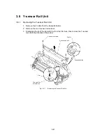
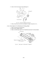
5. Push down on the T-lever unit to align the slot hole with the shaft, then remove the
unit.
T-lever B
T cam roller
T-lever spring
Slot
T-lever unit
T-lever A
Fig. 3.12-2
Removing the T-lever Unit
Summary of Contents for LX-1200
Page 1: ...SERVICE MANUAL MODEL LX 1200 LX 300 ...
Page 2: ...COOL LAMINATOR SERVICE MANUAL MODEL LX 1200 LX 300 ...
Page 5: ...Chapter 1 SPECIFICATIONS ...
Page 9: ...Chapter 2 MECHANISMS ...
Page 20: ...Chapter 3 DISASSEMBLY PROCEDURES ...
Page 58: ...Chapter 4 ASSEMBLY PROCEDURES ...
Page 105: ...Chapter 5 ELECTRONIC CONTROLLERS ...
Page 127: ...Chapter 6 MAINTENANCE ...
Page 149: ...Chapter 7 TROUBLESHOOTING ...

