3-10
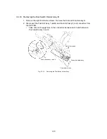
3.3.10 Removing the Dial Switch Holder Assy B
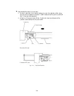
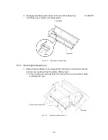
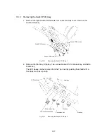
1. Remove the eight Dial holder screws. Remove the Dial switch holder assy B.
2. Disconnect the Push SW assy 1 (white) and Push SW assy 2 (red) connectors from
the SW PCB.
∗
Take care not to apply force to the connectors between switch and harness in
Push switch assy 1 and 2.
Dial holder screws
Push switch assy 1 and 2
Dial holder screws
Dial switch holder assy
Fig. 3.3-16
Removing the Dial Switch Holder Assy
Summary of Contents for LX-1200
Page 1: ...SERVICE MANUAL MODEL LX 1200 LX 300 ...
Page 2: ...COOL LAMINATOR SERVICE MANUAL MODEL LX 1200 LX 300 ...
Page 5: ...Chapter 1 SPECIFICATIONS ...
Page 9: ...Chapter 2 MECHANISMS ...
Page 20: ...Chapter 3 DISASSEMBLY PROCEDURES ...
Page 58: ...Chapter 4 ASSEMBLY PROCEDURES ...
Page 105: ...Chapter 5 ELECTRONIC CONTROLLERS ...
Page 127: ...Chapter 6 MAINTENANCE ...
Page 149: ...Chapter 7 TROUBLESHOOTING ...

