4-5
4.3.4
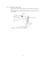
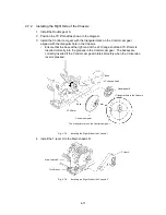
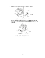
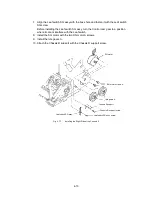
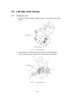
Installing the Main Chassis B
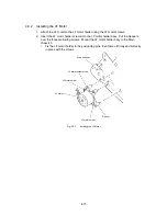
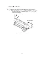
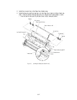
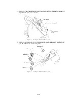
1. Install the two Cassette actuators.
2. Install the Leaf switch C3 (red) and C4 (yellow) assemblies using the Leaf switch
C3/C4 screws.
∗
Take care not to deform the tip of the leaf switch.
3. Engage the Leaf switch C3 and C4 harness into the hook under the Cassette holder,
then pass it through the Edging saddle under the Chassis B.
Cassette holder
ENC sensor
ENC sensor harness
Leaf switch
C3/C4 assy
Leaf switch C4 screws
Hook
Cassette
actuator
Harness
Leaf switch
C3 assy
Tape
The bottom face of
Cassette holder
Fig. 4.3-4
Installing the Main Chassis B
4. Tape the ENC sensor PCB harness inside the marked line (the side of the Cassette
holder hooks) under the Chassis B, then return the harness to the Edging saddle
under the Chassis B.
Summary of Contents for LX-1200
Page 1: ...SERVICE MANUAL MODEL LX 1200 LX 300 ...
Page 2: ...COOL LAMINATOR SERVICE MANUAL MODEL LX 1200 LX 300 ...
Page 5: ...Chapter 1 SPECIFICATIONS ...
Page 9: ...Chapter 2 MECHANISMS ...
Page 20: ...Chapter 3 DISASSEMBLY PROCEDURES ...
Page 58: ...Chapter 4 ASSEMBLY PROCEDURES ...
Page 105: ...Chapter 5 ELECTRONIC CONTROLLERS ...
Page 127: ...Chapter 6 MAINTENANCE ...
Page 149: ...Chapter 7 TROUBLESHOOTING ...

