


5-11
S
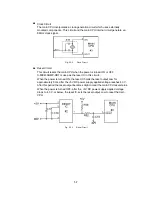
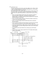
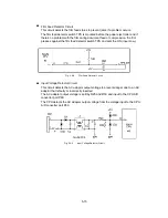
Switch Scan Circuit
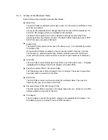
This circuit in the main CPU scans the status of the FEED
•
CUT
•
START
•
STOP
•
CONT
•
EXTRA BORDER key, and TRI switch (leaf switch) at 15 ms intervals to
continuously detect the status of each switch.
The circuit comprises a matrix of three output ports (P90, P91, P92) and three input
ports (P93 to P95). A Low signal is output at 5 ms intervals from one of the two
output ports and the switch status at that time is detected from the status of P93 to
P95).
•
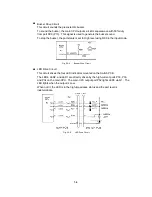
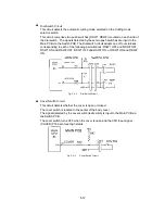
When the main CPU detects that the Feed switch was pressed, it starts the
document and film feed operation. The document and tape are fed in
approximately 0.5 mm intervals but the document and tape are fed continuously
while the Feed switch is held down.
•
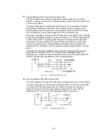
When the main CPU detects that the CUT switch was pressed, it operates the
X-cutter to start the film-cutting operation.
•
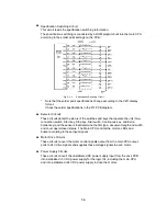
When the main CPU detects that the TRI switch was pressed, it starts the
trimming operation.
•
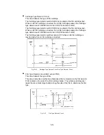
When the main CPU detects that the Start switch was pressed, it starts feeding
and compressing the document in the selected automatic cutting mode.
•
Automatic cutting operation is stopped when the main CPU detects that the Stop
switch was pressed. Automatic cutting operation restarts when the Start switch
is pressed again.
•
The continuous mode is selected when the Continuous key (CONT SW) is
pressed.
•
The Extra border mode is selected when the main CPU detects that the Extra
border key was pressed.
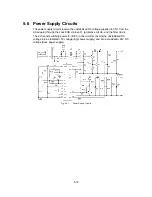
Fig. 5.4-1
Switch Scan Circuit
Summary of Contents for LX-1200
Page 1: ...SERVICE MANUAL MODEL LX 1200 LX 300 ...
Page 2: ...COOL LAMINATOR SERVICE MANUAL MODEL LX 1200 LX 300 ...
Page 5: ...Chapter 1 SPECIFICATIONS ...
Page 9: ...Chapter 2 MECHANISMS ...
Page 20: ...Chapter 3 DISASSEMBLY PROCEDURES ...
Page 58: ...Chapter 4 ASSEMBLY PROCEDURES ...
Page 105: ...Chapter 5 ELECTRONIC CONTROLLERS ...
Page 127: ...Chapter 6 MAINTENANCE ...
Page 149: ...Chapter 7 TROUBLESHOOTING ...