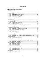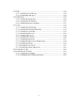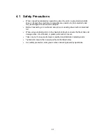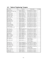
4-12
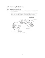
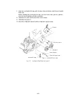
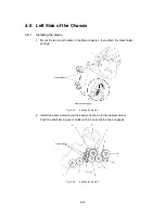
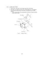
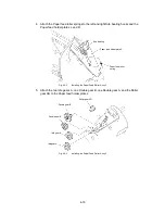
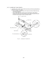
5. Install the T-lever B, T-cam roller, and T-cam spring onto T-lever A.
T-lever A
T-cam spring
T-lever B
T-cam roller
Fig. 4.7-5
Installing the Right Side of the Chassis 3
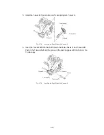
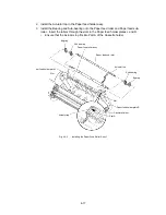
6. Insert the T-lever shaft into the shaft holes in the Main chassis R and T-lever A/B.
Push in the T-lever shaft until the groove in the shaft engages with the hook on the
T-cutter assy.
T-lever A
T-cutter assy
Groove
T-lever B
T-lever shaft
Fig. 4.7-6
Installing the Right Side of the Chassis 4
Summary of Contents for LX-1200
Page 1: ...SERVICE MANUAL MODEL LX 1200 LX 300 ...
Page 2: ...COOL LAMINATOR SERVICE MANUAL MODEL LX 1200 LX 300 ...
Page 5: ...Chapter 1 SPECIFICATIONS ...
Page 9: ...Chapter 2 MECHANISMS ...
Page 20: ...Chapter 3 DISASSEMBLY PROCEDURES ...
Page 58: ...Chapter 4 ASSEMBLY PROCEDURES ...
Page 105: ...Chapter 5 ELECTRONIC CONTROLLERS ...
Page 127: ...Chapter 6 MAINTENANCE ...
Page 149: ...Chapter 7 TROUBLESHOOTING ...

