3-32
3.15 Trimming Mechanism
3.15.1 Disassembling the Trimming Mechanism
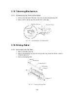
1. Remove the Leaf switch TRI screw, then remove the Leaf switch assy TRI.
2. Remove the T-cutter screw, then remove the T-cutter assy.
Leaf switch TRI screw
Leaf switch TRI assy
T-cutter screw
T-cutter unit
Fig. 3.15-1
Disassembling the Trimming Mechanism
3.16 Driving Roller
3.16.1 Removing the Driving Roller
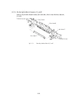
1. Remove the Roller gear CD.
2. Remove the Retaining ring, push the Driving roller assy toward the left then remove
it from the right end.
3. Remove the Bearings R/L.
Bearing R
Roller gear CD
Retaining ring
Driving roller assy
Retaining ring
Bearing L
Fig. 3.16-1
Removing the Driving Roller
Summary of Contents for LX-1200
Page 1: ...SERVICE MANUAL MODEL LX 1200 LX 300 ...
Page 2: ...COOL LAMINATOR SERVICE MANUAL MODEL LX 1200 LX 300 ...
Page 5: ...Chapter 1 SPECIFICATIONS ...
Page 9: ...Chapter 2 MECHANISMS ...
Page 20: ...Chapter 3 DISASSEMBLY PROCEDURES ...
Page 58: ...Chapter 4 ASSEMBLY PROCEDURES ...
Page 105: ...Chapter 5 ELECTRONIC CONTROLLERS ...
Page 127: ...Chapter 6 MAINTENANCE ...
Page 149: ...Chapter 7 TROUBLESHOOTING ...

