Phoenix 440-ML, Operating Manual
The Phoenix 440-ML Operating Manual is your essential guide to unlock the full potential of this remarkable product. Download the manual for free from our website and discover step-by-step instructions, tips, and troubleshooting advice to ensure seamless operation. Navigate to manualshive.com to access your free downloadable manual now!
Share
Download


Reviews:
No comments
Related manuals for 440-ML
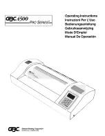
4500
Brand: GBC Pages: 11

Masterpiece 550
Brand: D&K Pages: 12

ES-1315
Brand: Royal Sovereign Pages: 24

Fusion Plus 7000 L
Brand: GBC Pages: 24
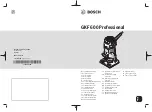
GKF 600 Professional
Brand: Bosch Pages: 199

Lunar 95
Brand: Fellowes Pages: 12

SpeedLAM A3
Brand: Opus Pages: 12

uniLAM A3
Brand: Opus Pages: 6

Coverator
Brand: Opus Pages: 4

uniLAM A4
Brand: Opus Pages: 12

rolLAM 380
Brand: Opus Pages: 12

RolLAM 380 Super
Brand: Opus Pages: 19

AutoLAM A3
Brand: Opus Pages: 19

MF1700-M1+
Brand: Mefu Pages: 11

MF1600-M1
Brand: Mefu Pages: 11

Brilliant Wonders 25597-70X-000
Brand: CMP Pages: 10

LM-420H
Brand: Aurora Pages: 1

NB-1900N
Brand: Royal Sovereign Pages: 15


