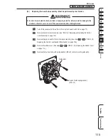
– Must be performed by a technician –
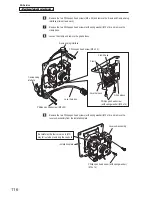
– Must be performed by a technician –
101
Service
8B. Service
Test Mode
Troubleshooting
(4) Removing and Installing the Power Panel Assembly – Must be performed by a technician –
z
z
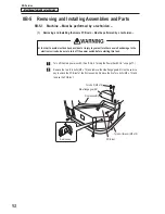
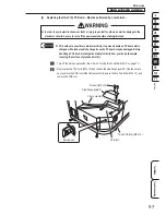
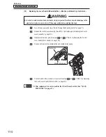
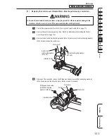
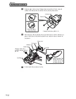
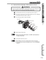
In order to avoid electric shock, accident or injury to yourself or others as well as damage to the
electronic circuits, be sure to turn off the power switch before starting this task.
Turn off the main power switch. (See “8A-2-3 Turning the Power Switch On” on page 77.)
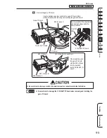
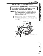
Remove the two Torx bolts (M5 x 12) and remove the side flange guard R.
Remove the four Torx bolts (black) (M5 x 12) and remove the PCB roof case.
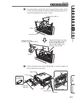
Use the service key to unlock the PCB roof of the front assembly. Remove the five Torx bolts
(M5 x 12), and remove the PCB roof. (See steps
of “8B-5-1 “(1) Removing and Installing
the Game PC Board” on page 92.)
PCB roof case
Side flange guard R
Torx bolt (black) (M5 x 12)
Torx bolt (M5 x 12)
Torx bolt (black) (M5 x 12)
Bottom part of the control lever
inside the front assembly
Pull forward and remove.
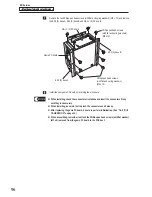
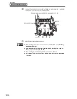
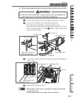
Loosen the two nuts with washers (M5), then lift up the power panel assembly slightly and pull
it forward to remove it.
Power panel assembly
Switching regulator (12 V)
Switching regulator (24 V)
Switching regulator
(5 V)
Nut with washer (M5)
Connector
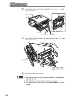
To install, perform the procedure in reverse.
z
z
When installing, check the connector orientations and insert the connectors firmly
until they lock securely.
z
z
When installing, be careful not to pinch the connectors and harness.

