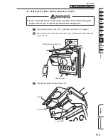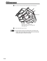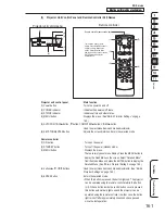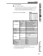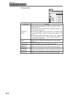
– Must be performed by a technician –
– Must be performed by a technician –
157
Service
8B. Service
Test Mode
Troubleshooting
(2) Lateral Adjustment – Must be performed by a technician –
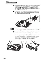
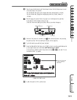
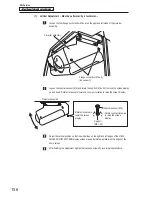
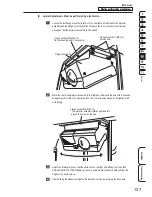
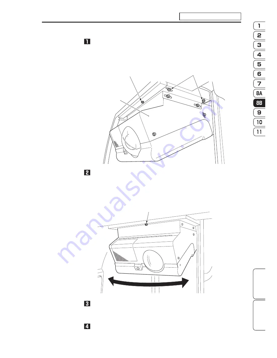
Loosen the four flange socket bolts (M6 x 12) on the right and left sides of the projector
assembly and the flange socket bolt (M6 x 12) above the lens. Loosen each screw just
enough so that the projector assembly can be moved.
Flange socket bolt (M6 x 12)
(loosen only)
Flange socket bolt (M6 x 12)
(functions as the axis) (loosen only)
Projector assembly
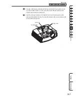
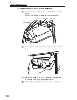
Move the rear of the projector assembly to the right and left around the axis of the loosened
flange socket bolt (M6 x 12) above the lens. The screen display moves to the right and left
accordingly.
Flange socket bolt (M6 x 12)
* The projector assembly rotates right and left
around this screw as the axis.
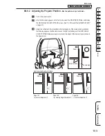
Adjust the lateral position so that the white lines on the right and left edges of the VIEW
ANGLE ADJUST PATTERN display screen are approximately the same distance from the
edges of the dome screen.
After finishing the adjustment, tighten the loosened screws by reversing the procedure.

