– Must be performed by a technician –
– Must be performed by a technician –
116
8B. Service
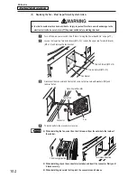
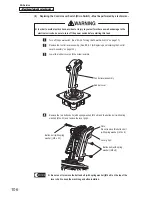
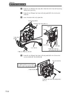
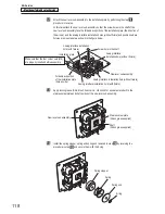
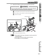
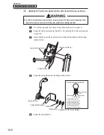
Remove the two Phillips pan head screws (M3 x 20) and remove the X-axis and Y-axis analog
interfaces (two screws each).
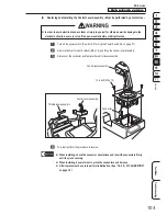
Remove the two Phillips pan head screws (with spring washer) (M5 x 14) and remove the
clamp base.
Loosen the clamp and remove the grip harness.
X-axis analog interface
Y-axis analog
interface
Phillips pan head screw (M3 x 20)
Phillips pan head screw (M3 x 20)
Lever harness
Phillips pan head screw
(with spring washer) (M5 x 14)
Lever harness
Clamp
Clamp base
Grip harness
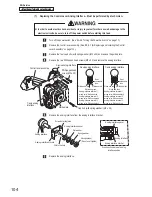
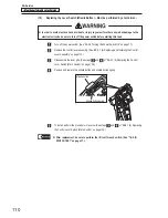
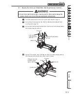
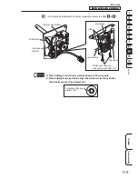
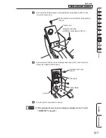
Remove the two Phillips pan head screws (with spring washer) (M5 x 14) and remove the
lever sub-assembly from the installation plate.
Lever sub-assembly
Installation plate
Phillips pan head screw (with spring washer)
(M5 x 14)
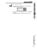
Be careful as the four corner nuts (M5)
may fall out when removing the cap bolts

