


– Must be performed by a technician –
– Must be performed by a technician –
104
8B. Service
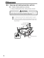
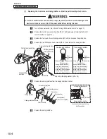
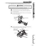
(7) Replacing the Control Lever Analog Interface – Must be performed by a technician –
z
z
In order to avoid electric shock, accident or injury to yourself or others as well as damage to the
electronic circuits, be sure to turn off the power switch before starting this task.
Turn off the power switch. (See “8A-2-3 Turning the Power Switch On” on page 77.)
Remove the control lever assembly. (See “8B-5-1 (6) Replacing and Installing the Control
Lever Assembly” on page 103.)
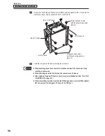
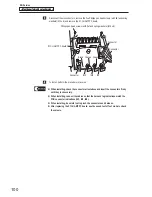
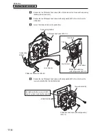
Remove the four cap bolts (with spring washer) (M5 x 35) and remove the guide plate.
Remove the two Phillips pan head screws (M3 x 20) and remove the analog interface.
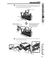
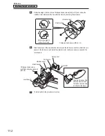
X-axis analog interface
Y-axis analog
interface
Phillips pan head
screw (M3 x 20)
Control lever assembly
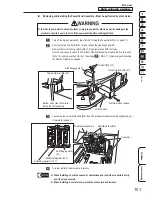
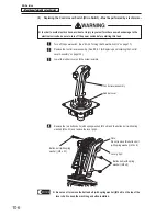
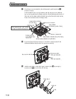
Analog interface terminal 1
wiring color: White and red
Analog interface terminal 2
wiring color: White and green
Analog interface terminal 3
wiring color: White and black
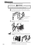
Analog interface terminal 1
wiring color: White and black
Analog interface terminal 2
wiring color: White and blue
Analog interface terminal 3
wiring color: White and red
Guide plate
Cap bolt (with spring washer) (M5 x 35)
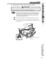
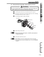
1
2
3
White and red
Heat-
shrinkable
tube
X-axis analog interface
White and green
White and black
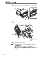
1
2
3
White and black
Heat-
shrinkable
tube
Y-axis analog interface
White and blue
White and red
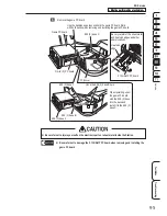
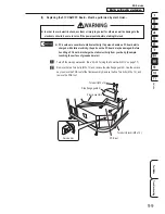
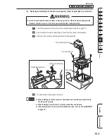
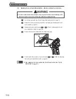
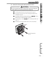
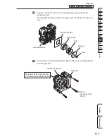
Remove the analog interface from the analog interface bracket.
Analog interface
Analog interface bracket
Flat washer
Spring washer
Hexagonal nut
(Do not over-tighten)
Analog interface spacer
Fit into the hole
Screw hole (tap) side
Analog interface spacer
Analog interface bracket
Cross sectional view of analog
interface portion
Analog interface
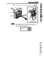
Replace the analog interface.