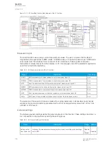
Measured input
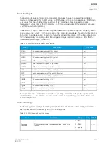
The function block uses analog current measurement values. However, when the peak-to-peak mode is
selected for the function's "Measured magnitude" setting , the values are taken directly from the
samples. The user can select the monitored magnitude to be equal either to RMS values, to TRMS
values from the whole harmonic specter of 32 components, or to peak-to-peak values. A -20ms
averaged value of the selected magnitude is used for pre-fault data registering.
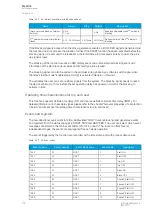
Table. 5.3.2 - 48. Measurement inputs of the I> function.
Signal
Description
Time base
IL1RMS
RMS measurement of phase L1 (A) current
5ms
IL2RMS
RMS measurement of phase L2 (B) current
5ms
IL3RMS
RMS measurement of phase L3 (C) current
5ms
IL1TRMS
TRMS measurement of phase L1 (A) current
5ms
IL2TRMS
TRMS measurement of phase L2 (B) current
5ms
IL3TRMS
TRMS measurement of phase L3 (C) current
5ms
IL1PP
Peak-to-peak measurement of phase L1 (A) current
5ms
IL2PP
Peak-to-peak measurement of phase L2 (B) current
5ms
IL3PP
Peak-to-peak measurement of phase L3 (C) current
5ms
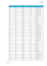
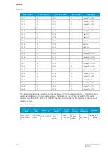
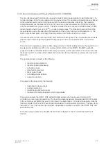
The selection of the used AI channel is made with a setting parameter. In all possible input channel
variations the pre-fault condition is presented with a 20 ms averaged history value from -20 ms
from START or TRIP event.
General settings
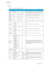
The following general settings define the general behavior of the function. These settings are static i.e.
it is not possible to change them by editing the setting group.
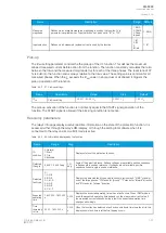
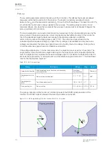
Table. 5.3.2 - 49. General settings of the function.
Name
Range
Step Default
Description
Setting control from
comm bus
1:
Disabled
2: Allowed
-
1:
Disabled
Activating this parameter allows changing the pick-up level of the
protection stage via SCADA.
Measured magnitude
1: RMS
2: TRMS
3: Peak-to-
peak
-
1: RMS
Defines which available measured magnitude is used by the function.
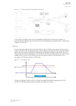
Pick-up
The
I
set
setting parameter controls the pick-up of the I> function. This defines the maximum allowed
measured current before action from the function. The function constantly calculates the ratio
between the
I
set
and the measured magnitude (
I
m
) for each of the three phases. The reset ratio of 97 %
is built into the function and is always relative to the
I
set
value. The setting value is common for all
measured phases, and when the
I
m
exceeds the
I
set
value (in single, dual or all phases) it triggers the
pick-up operation of the function.
A
AQ
Q-F205
-F205
Instruction manual
Version: 2.04
100
© Arcteq Relays Ltd
IM00013
Summary of Contents for AQ F205
Page 1: ...AQ F205 Feeder protection IED Instruction manual ...
Page 2: ......

