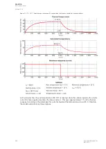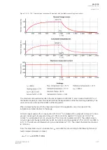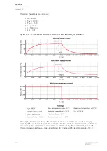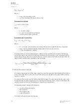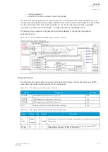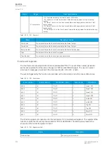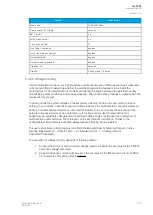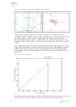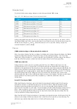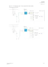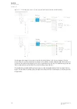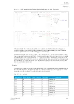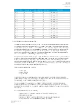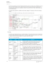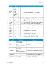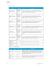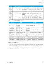
Figure. 5.3.20 - 168. Frequency reference channels.
For example, let us say a 500 A current is measured on the primary side while the fixed frequency is set
to 50 Hz. This results in the frequency dropping to 46 Hz, while the actual current measurement would
be 460 A. Therefore, the system would have an error of 40 A.
Events
The voltage memory function (abbreviated "M1VT" in event block names) generates events from the
status changes in various activities. The user can select which event messages are stored in the main
event buffer: ON, OFF, or both.
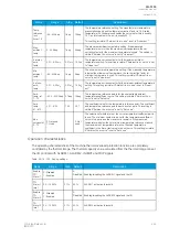
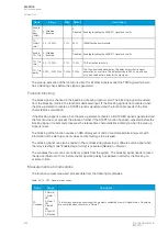
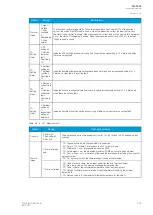
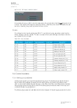
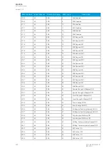
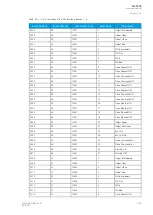
Table. 5.3.20 - 166. Event codes.
Event number
Event channel
Event block name
Event code
Description
12160
190
M1VT1
0
Voltage memory enabled
12161
190
M1VT1
1
Voltage memory disabled
12162
190
M1VT1
2
Voltage low detected ON
12163
190
M1VT1
3
Voltage low detected OFF
12164
190
M1VT1
4
Current high detected ON
12165
190
M1VT1
5
Current high detected OFF
12166
190
M1VT1
6
Frequency tracked from CT ON
12167
190
M1VT1
7
Frequency tracked from CT OFF
12168
190
M1VT1
8
Using Voltage memory ON
12169
190
M1VT1
9
Using Voltage memory OFF
12170
190
M1VT1
10
Voltage memory blocked ON
12171
190
M1VT1
11
Voltage memory blocked OFF
5.4 Control functions
5.4.1 Setting group selection
All relay types support up to eight (8) separate setting groups. The Setting group selection function
block controls the availability and selection of the setting groups. By default, only Setting group 1
(SG1) is active and therefore the selection logic is idle. When more than one setting group is enabled,
the setting group selector logic takes control of the setting group activations based on the logic and
conditions the user has programmed.
The following figure presents a simplified function block diagram of the setting group selection function.
A
AQ
Q-F205
-F205
Instruction manual
Version: 2.04
240
© Arcteq Relays Ltd
IM00013
Summary of Contents for AQ F205
Page 1: ...AQ F205 Feeder protection IED Instruction manual ...
Page 2: ......

