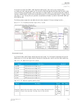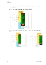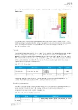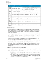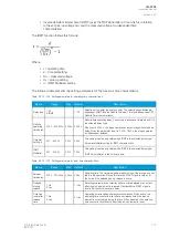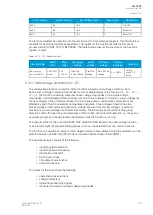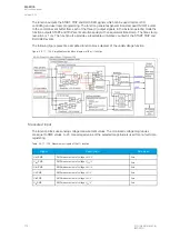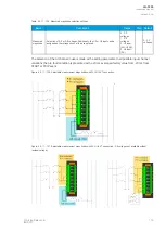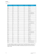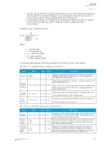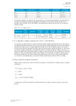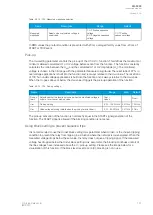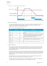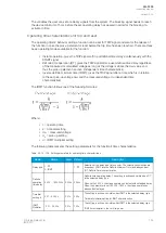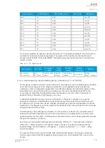
Table. 5.3.11 - 115. Register content.
Date and time
Event
code
Fault
type
Pre-trigger
voltage
Fault
voltage
Pre-fault
voltage
Trip time
remaining
Used SG
dd.mm.yyyy
hh:mm:ss.mss
5696-5895
Descr.
A…A-
B-C
Start/Trip
-20ms voltage
Start/Trip
voltage
Start -200ms
voltage
0 ms...1800s
Setting
group 1...8
active
5.3.12 Neutral overvoltage protection (U0>; 59N)
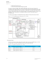
The neutral overvoltage function is used for non-directional instant and time-delayed earth fault
protection. Each device with a voltage protection module has four (4) available stages of the
function (U0>, U0>>, U0>>>, U0>>>>). The function constantly measures phase-to-earth voltage
magnitudes and calculates the zero sequence component. Neutral overvoltage protection is scaled
to line-to-line RMS level. When the line-to-line voltage of a system is 100 V in the secondary side, the
earth fault is 100 % of the
U
n
and the calculated zero sequence voltage reaches 100/
√
3 V = 57.74 V.
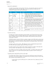
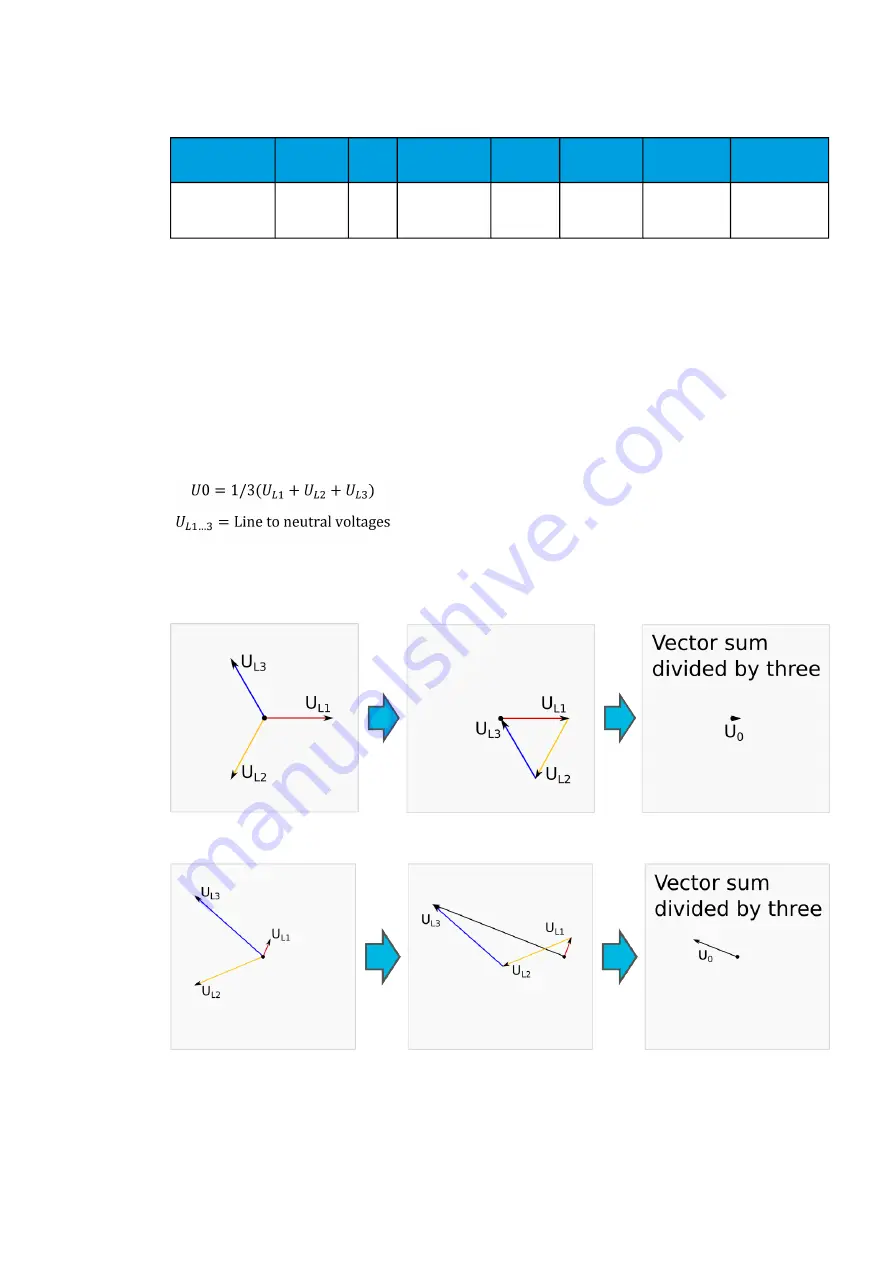
Below is the formula for symmetric component calculation (and therefore to zero sequence voltage
calculation).
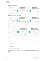
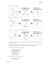
Below are some examples of zero sequence calculation.
Figure. 5.3.12 - 130. Normal situation.
Figure. 5.3.12 - 131. Earth fault in isolated network.
A
AQ
Q-F205
-F205
Instruction manual
Version: 2.04
© Arcteq Relays Ltd
IM00013
181
Summary of Contents for AQ F205
Page 1: ...AQ F205 Feeder protection IED Instruction manual ...
Page 2: ......

