5.4.7 Synchrocheck (ΔV/Δa/Δf; 25)
Checking the synchronization is important to ensure the safe closing of the circuit breaker between two
systems. Closing the circuit breaker when the systems are not synchronized can cause several
problems such as current surges which damage the interconnecting elements. The synchrocheck
function has three stages: SYN1, SYN2 and SYN3. Their function and availability of these
stages depend on which voltage channels are set to "SS" mode or not. Voltage measurement settings
are located at
Measurements
→
Transformers
→
VT module. SYN1 also includes synchroswitching.
When synchroswitching is used, the function automatically closes the breaker when both sides of the
breaker are synchronized.
When only U3 or U4 voltage measurement channel has been set to "SS" mode:
• SYN1 – Supervises the synchronization condition between the channel set to "SS" mode and
the selected system voltage (UL1, UL2, UL3, UL12, UL23 or UL31). Synchroswitch is
available.
• SYN2 – Not active and not visible.
• SYN3 – Not active and not visible.
When both U3 and U4 have been set to "SS" mode:
• SYN1 – Supervises the synchronization condition between the U3 channel and the selected
system voltage (UL1, UL2, UL3, UL12, UL23 or UL31). Synchroswitch is available.
• SYN2 – Supervises the synchronization condition between the U4 channel and the selected
system voltage (UL1, UL2, UL3, UL12, UL23 or UL31).
• SYN3 – Supervises the synchronization condition between the channels U3 and U4.
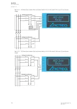
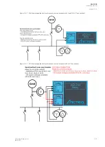
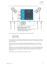
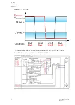
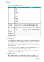
The seven images below present three different example connections and four example applications of
the synchrocheck function.
Figure. 5.4.7 - 203. Example connection of the synchrocheck function (3LN+U4 mode, SYN1 in use, UL1 as reference voltage).
A
AQ
Q-F205
-F205
Instruction manual
Version: 2.04
© Arcteq Relays Ltd
IM00013
299
Summary of Contents for AQ F205
Page 1: ...AQ F205 Feeder protection IED Instruction manual ...
Page 2: ......


