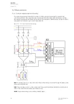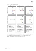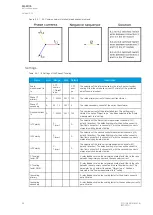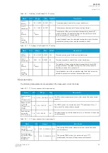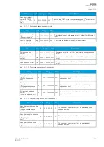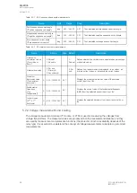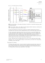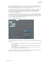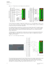
For the measurements to be correct the user needs to ensure that the measurement signals are
connected to the correct inputs, that the current direction is connected to the correct polarity, and that
the scaling is set according to the nominal values of the current transformer.
The relay calculates the scaling factors based on the set values of the CT primary, the CT secondary
and the nominal current settings. The relay measures the secondary current, the current output from
the current transformer installed into application's primary circuit. The rated primary and secondary
currents of the CT need to be set for the relay to "know" the primary and per-unit values. With motors
and other specific electrical apparatus protections, the motor's nominal current should be set for the
values to be in per unit with regards to the apparatus nominal instead of the CT nominal. This is not
always mandatory as some relays still require manual calculations for the correct settings; however,
setting the motors nominal current makes motor protection much easier and more straightforward. In
modern protection devices this scaling calculation is done internally after the current transformer's
primary current, secondary current and motor nominal current are set.
Normally, the primary current ratings for phase current transformers are 10 A, 12.5 A, 15 A, 20 A, 25
A, 30 A, 40 A, 50 A, 60 A and 75 A as well as their decimal multiples, while the secondary current
ratings are 1 A and 5 A. Other, non-standard ratings can be directly connected as the scaling settings
are flexible and have large ranges. For example, the ring core current transformer ratings may vary.
Ring core current transformers are commonly used for sensitive earth fault protection and their rated
secondary current may be as low as 0.2 A in some cases.
The following chapter is an example on how to set the scaling of the current measurements for the
selected current transformer and system load.
Example of CT scaling
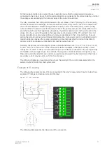
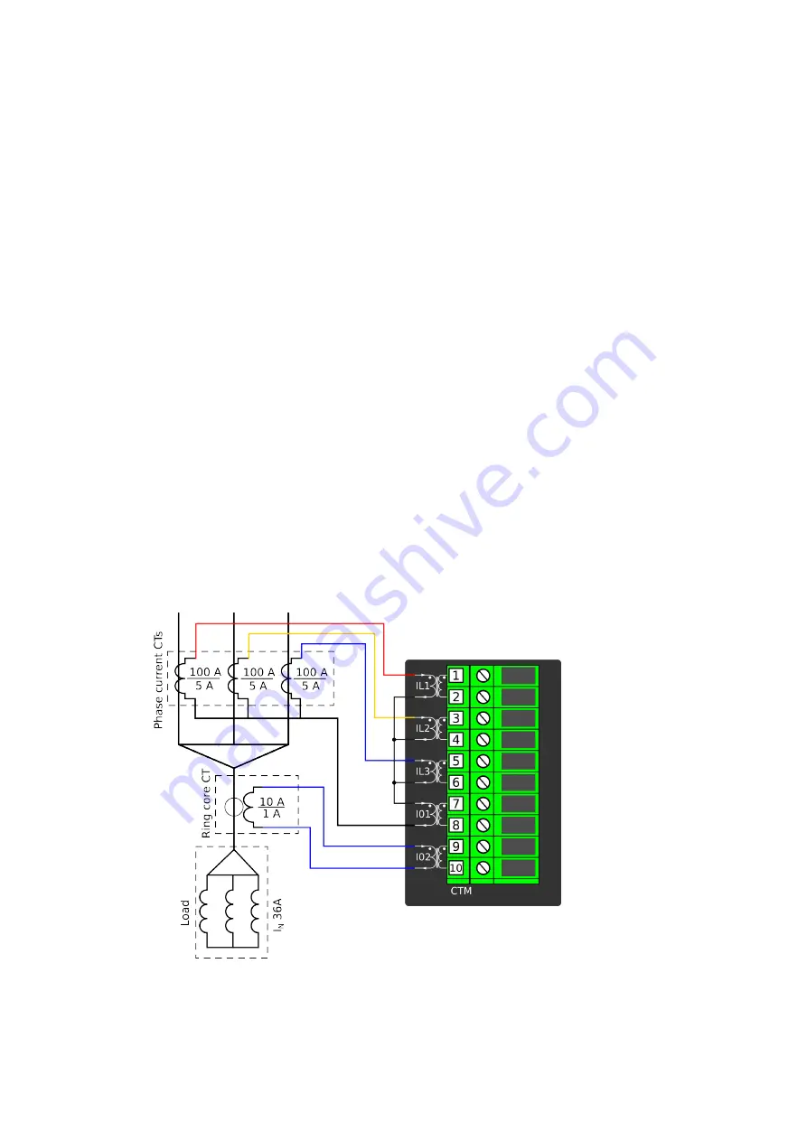
The following figure presents how CTs are connected to the relay's measurement inputs. It also shows
example CT ratings and nominal current of the load.
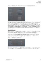
Figure. 5.2.1 - 56. Connections.
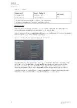
The following table presents the initial data of the connection.
A
AQ
Q-F205
-F205
Instruction manual
Version: 2.04
© Arcteq Relays Ltd
IM00013
57
Summary of Contents for AQ F205
Page 1: ...AQ F205 Feeder protection IED Instruction manual ...
Page 2: ......


