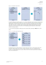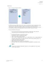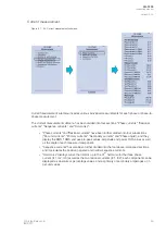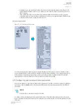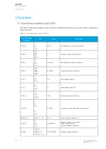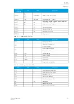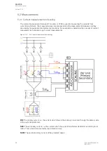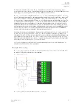
CT module
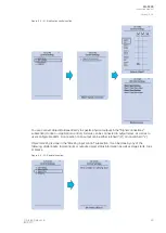
Figure. 4.7 - 42. CT module section.
The three main sections ("Phase CT scaling", "Residual I01 CT scaling" and "Residual I02 CT scaling")
determine the ratio of the used transformers. Additionally, the nominal values are also determined in
the
CT module submenu. Sometimes a mistake in the wiring can cause the polarity to be changed; in
such cases, you can invert the polarity of each phase current individually. The
CT module submenu
also displays additional information such as CT scaling factors and per-unit scaling factors.
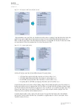
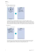
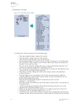
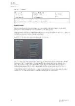
VT module
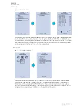
Figure. 4.7 - 43. VT module section.
Voltage transformer settings include voltage measurement mode selection, voltage transformer
nominal settings and voltage channel polarity switching. Voltage transformer setting defines what kind
of voltages are connected to the VT module card. The voltages are: three line-to-line voltages, three
line-to-neutral voltages, two line-to-line voltages leaving the third one free as additional voltage channel
for neutral voltage or synchrochecking. U4 channel can be set to work as residual voltage mode or
"SS" (system set) mode, which can be used for synchrochecking, synchronizing and other uses.
A
AQ
Q-F205
-F205
Instruction manual
Version: 2.04
© Arcteq Relays Ltd
IM00013
43
Summary of Contents for AQ F205
Page 1: ...AQ F205 Feeder protection IED Instruction manual ...
Page 2: ......

