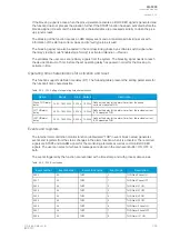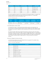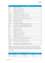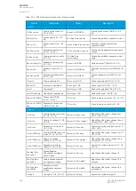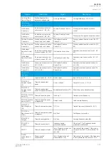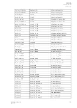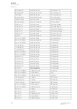
Signal
Description
Signal
Description
Pos./Neg./Zero
Seq volt.Angle
Positive/Negative/Zero
sequence voltage angle
Ux Angle difference
Ux angle difference (U1, U2, U3)
Resistive and
reactive currents
ILx Resistive
Current p.u.
ILx resistive current in per-
unit values (IL1, IL2, IL3)
Pos.seq. Resistive Current
Pri.
Primary positive sequence resistive
current
ILx Reactive
Current p.u.
ILx reactive current in per-
unit values (IL1, IL2, IL3)
Pos.seq. Reactive Current
Pri.
Primary positive sequence reactive current
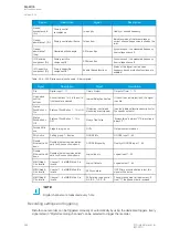
Pos.Seq. Resistive
Current p.u.
Positive sequence resistive
current in per-unit values
I0x Residual Resistive
Current Pri.
Primary residual resistive current I0x (I01,
I02)
Pos.Seq. Reactive
Current p.u.
Positive sequence reactive
current in per-unit values
I0x Residual Reactive
Current Pri.
Primary residual reactive current I0x (I01,
I02)
I0x Residual
Resistive Current
p.u.
I0x residual resistive current
in per-unit values (I01, I02)
ILx Resistive Current Sec.
Secondary resistive current ILx (IL1, IL2,
IL3)
I0x Residual
Reactive Current
p.u.
I0x residual ractive current
in per-unit values (I01, I02)
ILx Reactive Current Sec.
Secondary reactive current ILx (IL1, IL2,
IL3)
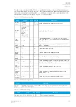
ILx Resistive
Current Pri.
Primary resistive current ILx
(IL1, IL2, IL3)
I0x Residual Resistive
Current Sec.
Secondary residual resistive current I0x
(I01, I02)
ILx Reactive
Current Pri.
Primary reactive current ILx
(IL1, IL2, IL3)
I0x Residual Reactive
Current Sec.
Secondary residual reactive current I0x
(I01, I02)
Power, GYB,
frequency
Lx PF
Lx power factor (L1, L2, L3)
Curve x Input
Input of Curve x (1, 2, 3, 4)
POW1 3PH
Apparent power
(S)
Three-phase apparent
power
Curve x Output
Output of Curve x (1, 2, 3, 4)
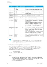
POW1 3PH
Apparent power
(S MVA)
Three-phase apparent
power in megavolt-amperes
Enablefbasedfunctions(VT1)
Enable frequency-based functions
POW1 3PH Active
power (P)
Three-phase active power
Track.sys.f.
Tracked system frequency
POW1 3PH Active
power (P MW)
Three-phase active power
in megawatts
Sampl.f. used
Used sample frequency
POW1 3PH
Reactive power
(Q)
Three-phase reactive power Tr f CH x
Tracked frequency (channels A, B, C)
POW1 3PH
Reactive power (Q
MVar)
Three-phase reactive power
in megavars
Alg f Fast
Fast frequency algorithm
POW1 3PH
Tan(phi)
Three-phase tangent phi
Alg f avg
Average frequency algorithm
POW1 3PH
Cos(phi)
Three-phase cosine phi
Frequency based
protections blocked
When true ("1"), all frequency-based
protections are blocked.
3PH PF
Three-phase power factor
f atm. Protections (when not
measurable returns to
nominal)
Frequency at the moment. If the system
nominal is set to 50 Hz, this will show "50
Hz".
Neutral
conductance G
(Pri)
Primary neutral
conductance
f atm. Display (when not
measurable is 0 Hz)
Frequency at the moment. If the frequency
is not measurable, this will show "0 Hz".
A
AQ
Q-F205
-F205
Instruction manual
Version: 2.04
© Arcteq Relays Ltd
IM00013
343
Summary of Contents for AQ F205
Page 1: ...AQ F205 Feeder protection IED Instruction manual ...
Page 2: ......


