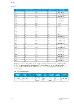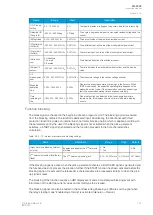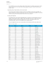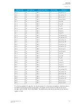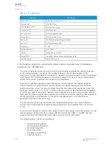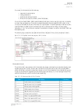
• threshold comparator
• angle check
• block signal check
• time delay characteristics
• output processing.
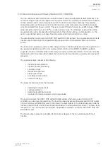
The inputs for the function are the following:
• operating mode selections
• setting parameters
• digital inputs and logic signals
• measured and pre-processed current magnitudes.
The function outputs the START, TRIP and BLOCKED signals which can be used for direct I/O
controlling and user logic programming. The function generates general time-stamped ON/OFF events
to the common event buffer from each of the three (3) output signals. In the instant operating mode the
function outputs START and TRIP events simultaneously with an equivalent time stamp. The time stamp
resolution is 1 ms. The function also provides a cumulative counter for the START, TRIP and BLOCKED
events.
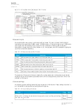
The following figure presents a simplified function block diagram of the directional earth fault function.
Figure. 5.3.5 - 92. Simplified function block diagram of the I0dir> function.
Measured input
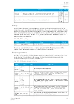
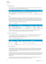
The function block uses analog current measurement values. The user can select the monitored
magnitude to be equal either to RMS values, to TRMS values, or to peak-to-peak values. TRMS mode
uses values from the whole harmonic spectrum of 32 components. Peak-to-peak mode picks
measurement values directly from the samples. A -20 ms averaged value of the selected magnitude is
used for pre-fault data registering.
The fault current angle is based on comparing the neutral voltage
U
0
angle to the residual current
I
0
angle. Both
I
0
and
U
0
must be above the squelch limit to be able to detect the angle. The squelch limit
for the
I
0
current is 0.01 x
I
n
and for the
U
0
voltage 0.01 x
U
n
.
A
AQ
Q-F205
-F205
Instruction manual
Version: 2.04
118
© Arcteq Relays Ltd
IM00013
Summary of Contents for AQ F205
Page 1: ...AQ F205 Feeder protection IED Instruction manual ...
Page 2: ......

