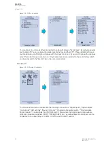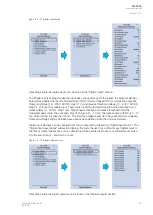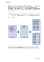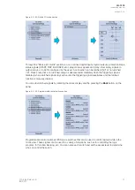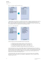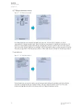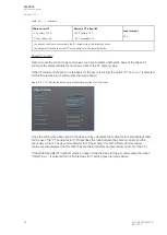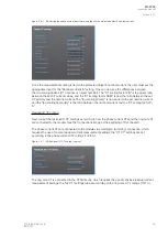
The
Impedance calculations submenu is divided into four sections: "Impedance calculation settings",
"Phase-to-phase impedances", "Phase-to-earth impedances" and "Positive sequence impedance". You
can activate impedance calculations in the first section. "Phase-to-phase impedances" display the
resistances and reactances of the three phase-to-phase connections, both primary and secondary, as
well as the primary and secondary impedances and impedance angles. "Phase-to-earth impedances"
displays the resistances and reactances of the three phases as well the primary and secondary
impedances and impedance angles. "Positive sequence impedance" displays the resistances and
reactances (both primary and secondary) of the positive sequence as well as its primary and
secondary impedances and the impedance angle.
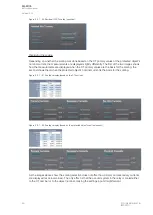
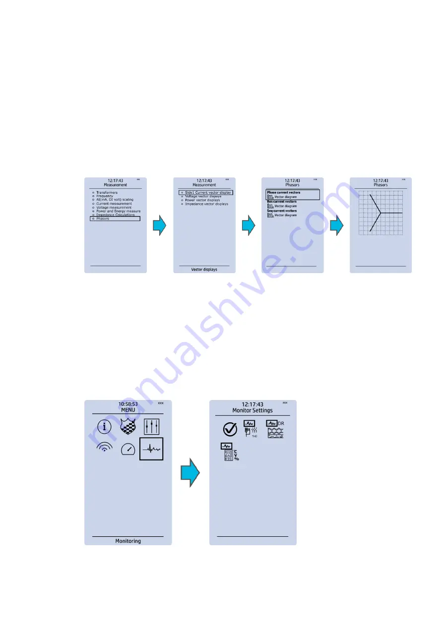
Phasors
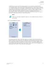
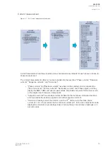
Figure. 4.7 - 49. Phasors submenu.
The
Phasors submenu holds the vector displays for voltages and currents, as well as the various
calculated components the IED may have (e.g. power, impedance). Phasors are helpful when solving
incorrect wiring issues.
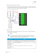
4.8 Monitoring menu
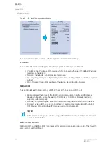
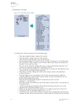
The
Monitoring main menu includes submenus (see the image below) for enabling the various
monitoring functions (
Monitors enabled), setting the various monitoring functions (Monitor functions),
controlling the disturbance recorder (
Disturbance REC) and accessing the device diagnostics (Device
diagnostics). The available monitoring functions depend on the type of the device in use.
Figure. 4.8 - 50. Monitoring menu view.
A
AQ
Q-F205
-F205
Instruction manual
Version: 2.04
48
© Arcteq Relays Ltd
IM00013
Summary of Contents for AQ F205
Page 1: ...AQ F205 Feeder protection IED Instruction manual ...
Page 2: ......

