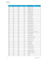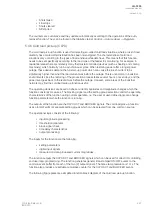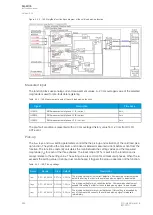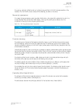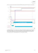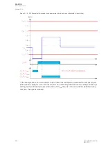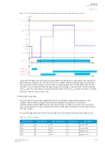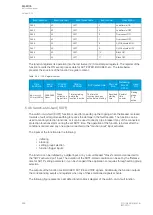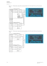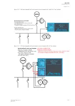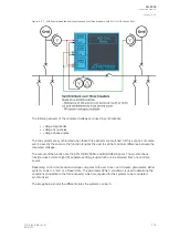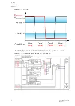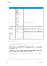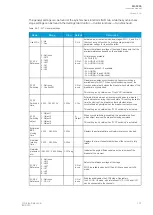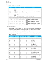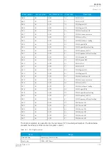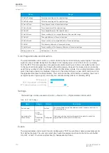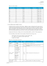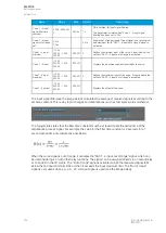
Figure. 5.4.6 - 202. Simplified function block diagram of the switch-on-to-fault function.
Input signals
The function block does not use analog measurement inputs. Instead, its operation is based entirely on
binary signal statuses.
Table. 5.4.6 - 194. Input signals.
Input
Description
Activate
input
The digital input or logic signal for the function to arm and start calculating the SOTF time. Any binary signal can be
used to activate the function and start the calculation. The rising edge of the signal is considered as the start of the
function.
Block
input
The input for blocking the function. Any binary signal can be used to block the function from starting.
Function
input
The function input activates the function's instant trip if applied when the function is calculating the SOTF time.
Settings
The switch-on-to-fault function has one setting and it determines how long the function remains active
after it has been triggered. If the inputs receive any of the set signals during this time, the function's trip
is activated.
Table. 5.4.6 - 195. Active settings.
Name
Range
Step
Default
Description
Release time for SOTF
0.000…1800.000s
0.005s
1.000s
The time the function is active after triggering.
Read-only parameters
The relay's
Info page displays useful, real-time information on the state of the protection function. It is
accessed either through the relay's HMI display, or through the setting tool software when it is
connected to the relay and its Live Edit mode is active.
A
AQ
Q-F205
-F205
Instruction manual
Version: 2.04
© Arcteq Relays Ltd
IM00013
297
Summary of Contents for AQ F205
Page 1: ...AQ F205 Feeder protection IED Instruction manual ...
Page 2: ......


