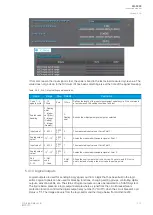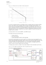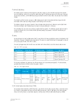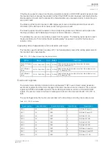
Signal
Description
Time base
U
L3
Ang
Angle of U
L3
voltage
5ms
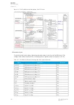
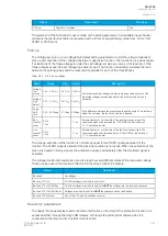
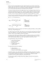
The selection of the AI channel in use is made with a setting parameter. In all possible input channel
variations the pre-fault condition is presented with a 20 ms averaged history value from -20 ms from
START or TRIP event.
Pick-up
The
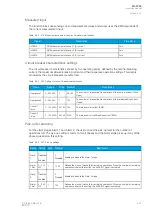
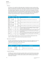
Voltage low pick-up and Voltage high detect setting parameters control the voltage-dependent
pick-up and activation of the voltage transformer supervision function. The function's pick-up activates,
if at least one of the three voltages is under the set
Voltage low pick-up value, or if at least two of the
three voltages exceed the set
Voltage high detect value. The function constantly calculates the ratio
between the setting values and the measured magnitude for each of the three phases.
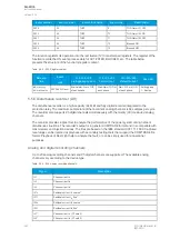
Table. 5.5.2 - 215. Pick-up settings.
Name
Range
Step
Default
Description
Voltage
low
pickup
0.05…0.50×U
n
0.01×U
n
0.05×U
n
If one the measured voltages is below low pickup value and two of the
measured voltages exceed high detect value the function's pick-up
activates.
Voltage
high
detect
0.01…1.10×U
n
0.01×U
n
0.80×U
n
Angle
shift
limit
2.00…90.00deg 0.10deg 5.00deg If the difference between the present angle and the angle 40 ms before is
below the set value, the function's pick-up is blocked.
Bus
fuse fail
check
0: No
1: Yes
-
1: Yes
Selects whether or not the state of the bus fuse is supervised. The
supervised signal is determined the "VTS MCB Trip bus" setting (
I/
O
→
Fuse failure inputs).
Line
fuse fail
check
0: No
1: Yes
-
1: Yes
Selects whether or not the state of the line fuse is supervised. The
supervised signal is determined by the "VTS MCB Trip line" setting (
I/
O
→
Fuse failure inputs).
The pick-up activation of the function is not directly equal to the START signal generation of the
function. The START signal is allowed if the blocking condition is not active. When the activation of the
pick-up is based on binary signals, the activation happens immediately after the monitored signal is
activated.
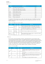
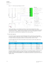
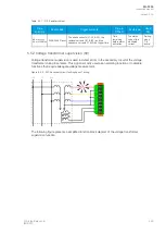
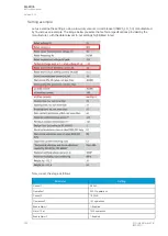
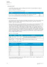
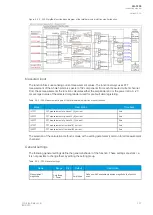
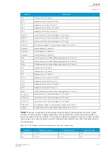
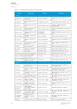
The voltage transformer supervision can also report several different states of the measured voltage.
These can be seen in the function's
INFO tab in the relay's HMI or in AQtivate.
Name
Description
Bus dead
No voltages.
Bus Live VTS Ok
All of the voltages are within the set limits.
Bus Live VTS Ok SEQ Rev
All of the voltages are within the set limits BUT
BUT the voltages are in a reversed sequence.
Bus Live VTS Ok SEQ Undef
Voltages are within the set limits BUT
BUT the sequence cannot be defined.
Bus Live VTS problem
Any of the VTS pick-up conditions are met.
Read-only parameters
The relay's
Info page displays useful, real-time information on the state of the protection function. It is
accessed either through the relay's HMI display, or through the setting tool software when it is
connected to the relay and its Live Edit mode is active.
A
AQ
Q-F205
-F205
Instruction manual
Version: 2.04
© Arcteq Relays Ltd
IM00013
327
Summary of Contents for AQ F205
Page 1: ...AQ F205 Feeder protection IED Instruction manual ...
Page 2: ......

